
Electrically controllable collimator in a laser resonator

a collimator and laser resonator technology, applied in the field of collimators for laser assemblies, can solve the problems of insufficient robustness, insufficient robustness, and insufficient cost for access networks

Active Publication Date: 2015-03-24
XIEON NETWORKS SARL
View PDF9 Cites 1 Cited by
  • Summary
  • Abstract
  • Description
  • Claims
  • Application Information

AI Technical Summary

Benefits of technology

The patent text describes a collimator that uses liquid lenses, which are low-cost technology commonly found in consumer applications like digital cameras. This collimator allows for easy and rapid adjustment of the laser assembly's phase, while also consuming low power. The control circuit of the laser controls the phase of the collimator based on two reference frequencies, making it highly stable and accurate. Overall, this invention provides an affordable and efficient solution for fine-tuning the laser assembly's phase.

Problems solved by technology

They are widely deployed in core networks but so far have been too expensive for use in access networks, i.e. in data transmission devices located at the customers' premises.
Using the laser temperature to fine-adjust the phase requires a costly Peltier cooler / heater and has the additional disadvantage of a slow response speed.
As an alternative a cavity mirror may be moved by using a piezo-electric element which requires moving parts and therefore is expensive and not robust enough.
Due to coupling losses between chips the gain and phase control section should be integrated on a single chip which requires sophisticated lithography which again is costly.

Method used


Image

  • Electrically controllable collimator in a laser resonator
  • Electrically controllable collimator in a laser resonator
  • Electrically controllable collimator in a laser resonator

Examples


Embodiment Construction

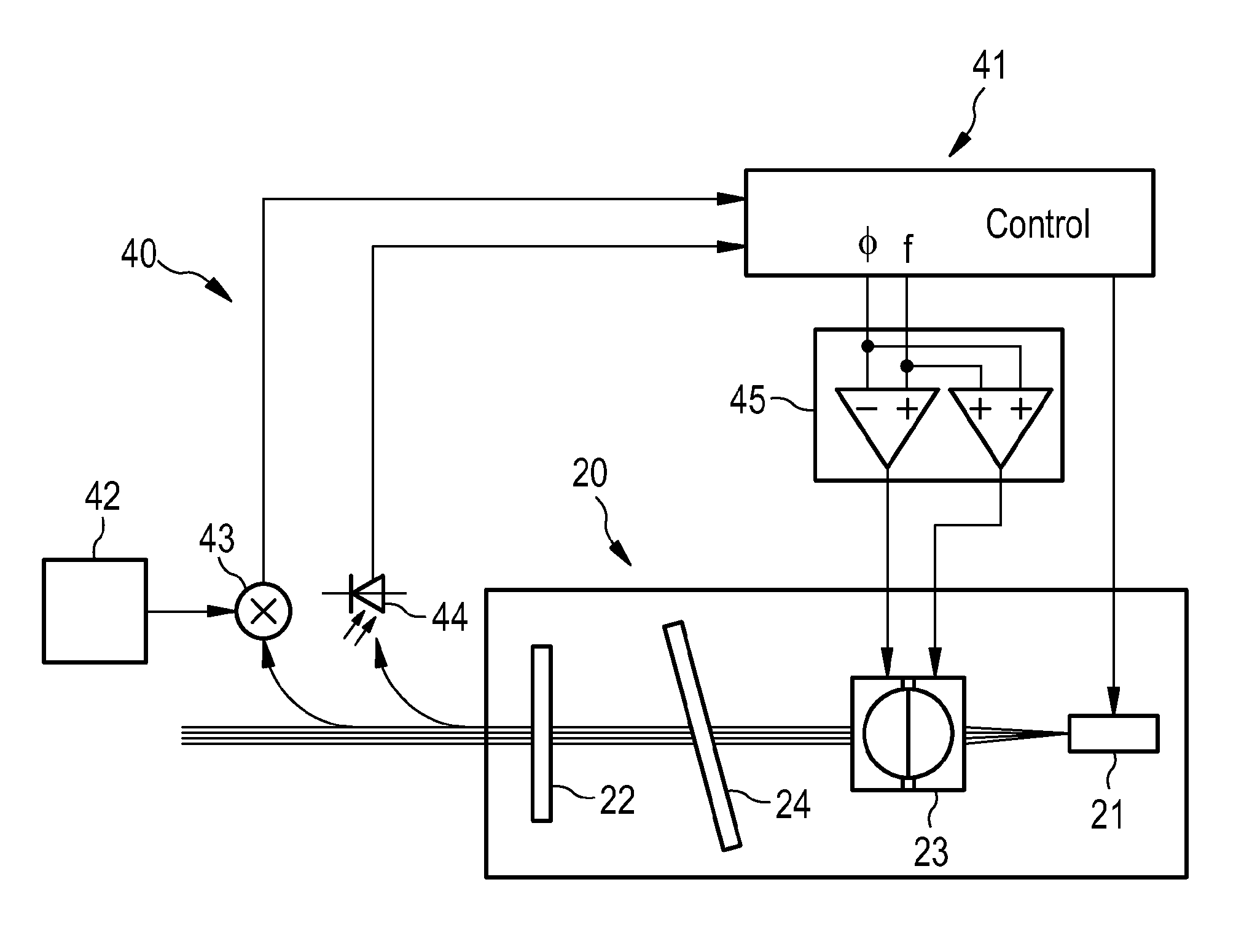
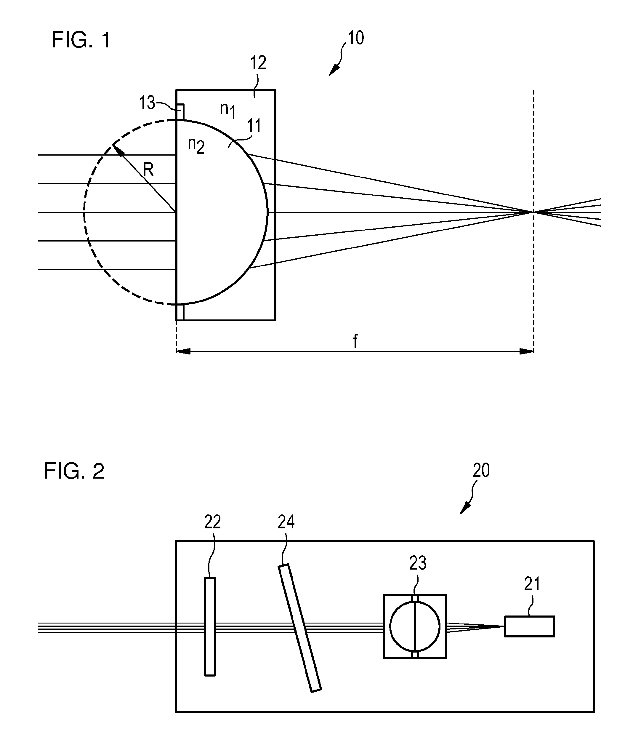
[0026]FIG. 2 shows a laser 20 using a collimator 23 according to the invention. A gain medium 21 and a semitransparent mirror 22 are located at opposite ends of a laser cavity. Since the gain medium 21 emits a mode having a finite angle, a collimator 23 is provided to collimate the light emitted by the gain medium 21. The focal length of the collimator 23 is chosen such that light reflected from the semitransparent mirror 22 is focussed at the same angle as the angle with which the gain medium 21 emits light. The laser 20 may further include a dielectric filter 24 which provides a coarse tuning mechanism which selects one of the cavity modes. The fine tuning of the modes is then done by phase adjustment.

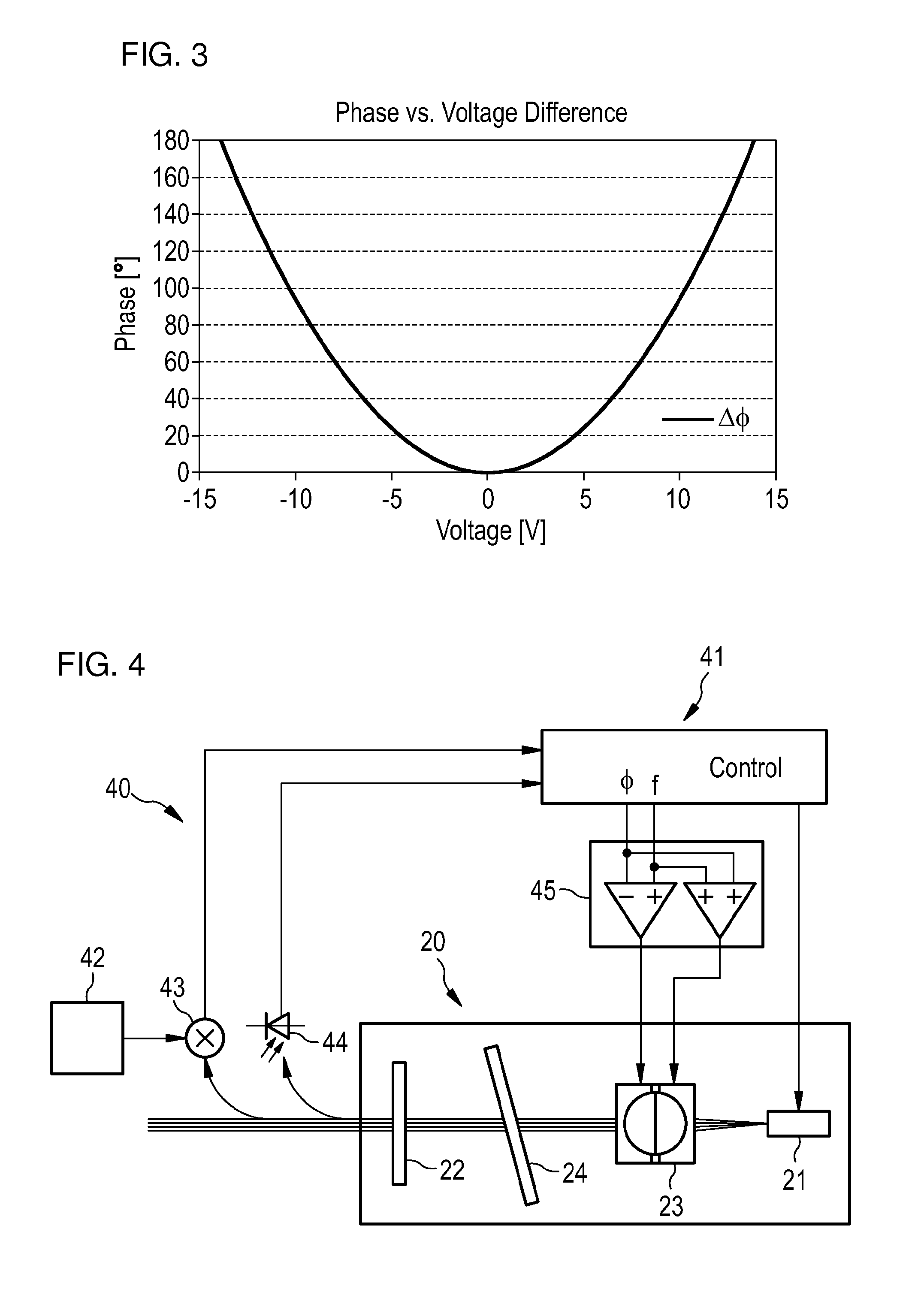
[0027]FIG. 3 shows a diagram illustrating the dependence of phase angle on the input voltage of an exemplary liquid lens (e.g. the liquid lens 10 of FIG. 1) comprising a drop of 1-bromo-dodecane in an aqueous Na2SO4 solution. The optical power of a liquid lens 10 depends linearly on ...


PUM


Abstract

A collimator for a laser assembly includes a first electrostatically controllable liquid lense having a first optical axis and a second electrostatically controllable liquid lense having a second optical axis aligned with the first optical axis. A laser is provided and has such a collimator. Finally, a transmitter uses the laser for optical data transmission.

Description

TECHNICAL FIELD OF THE INVENTION[0001]The invention provides a collimator for a laser assembly, such a laser assembly and a transmitter for an optical data network comprising such a laser assembly.BACKGROUND OF THE INVENTION[0002]Tunable lasers are in high demand in optical communication systems because of their versatility. They are widely deployed in core networks but so far have been too expensive for use in access networks, i.e. in data transmission devices located at the customers' premises. Designs which are currently in use typically rely on sophisticated optoelectronic laser chips. An alternative is the extended cavity laser (ECL) which uses a low-cost gain chip combined with a mechanically tuned thin-film filter and a ball lens for collimation. The mechanically tunable laser design commonly offers three parameters with which the laser wavelength can be adjusted: the filter position (coarse-tuning of the laser gain profile), the laser current (fine-tuning of the cavity modes...

Claims


Application Information

Patent Timeline
Patent Type & Authority Patents(United States)
IPC IPC(8): H04B10/00G02B3/14G02B26/00H01S3/106H01S3/13H01S3/137H01S5/0687H01S5/14
CPCH01S3/1307G02B3/14G02B26/005H01S3/137H01S3/1062H01S5/0687H01S5/141
Inventor TREYER, THOMASSMOLORZ, SYLVIA
Owner XIEON NETWORKS SARL
Learn More