Blade driving mechanism for a table saw
- Summary
- Abstract
- Description
- Claims
- Application Information
AI Technical Summary
Benefits of technology
Problems solved by technology
Method used
Image
Examples
Embodiment Construction
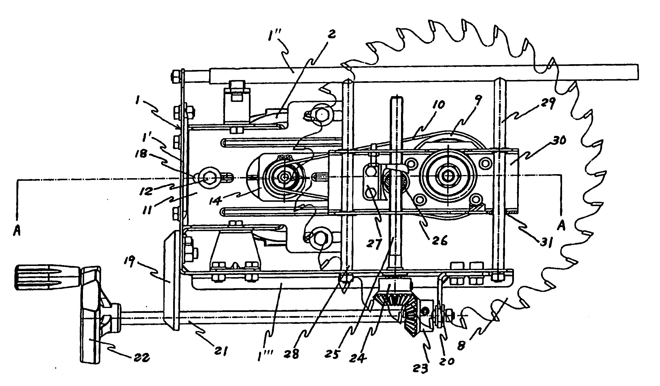
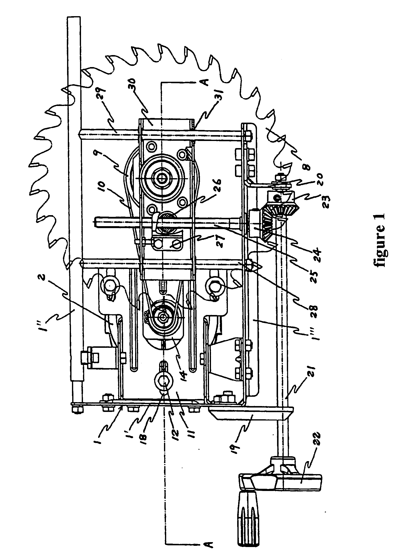
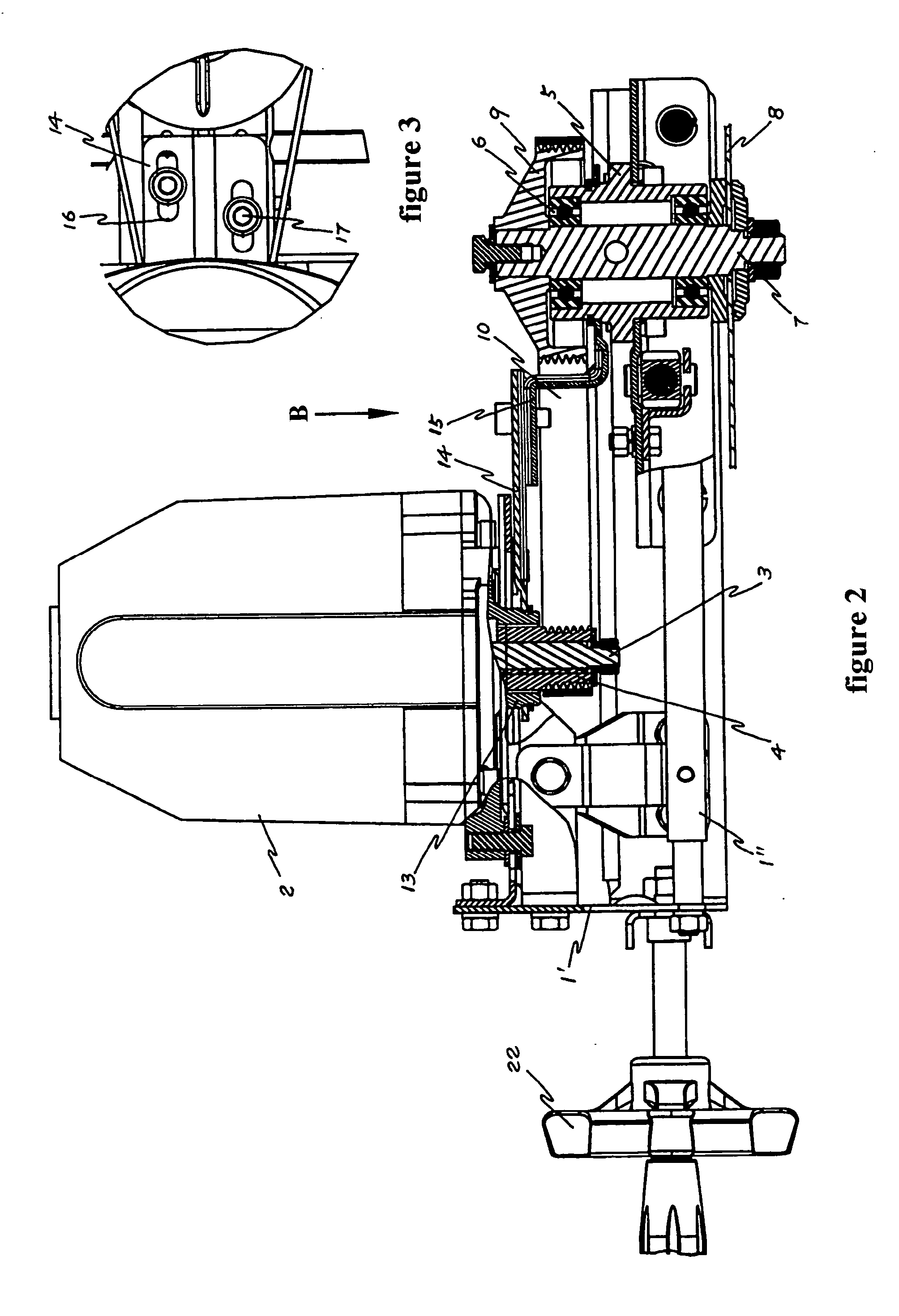
[0020] An embodiment of a table saw according to the present invention will now be described with reference to the figures, wherein like numbers represent like parts.
[0021] As shown in FIGS. 1 to 4, a table saw of the present invention comprises a main frame 1, a working table (not shown) mounted onto the main frame, a blade driving mechanism mounted to the main frame, and a saw blade 8 mounted to and driven by the blade driving mechanism.
[0022] The main frame 1 is composed of several frame parts, such as a vertical plate part 1′, a horizontal bar 1″ mounted to the top end of the vertical plate part 1′, and a horizontal plate part 1′″ mounted to or integrally formed with the vertical plate part 1′ at the lower end of the vertical plate part 1′. All the frame parts are used for mounting and supporting various parts of the blade driving mechanism.
[0023] The saw blade 8 is driven by the blade driving mechanism to rotate. The height of the saw blade 8, or the height of the part of th...
PUM
| Property | Measurement | Unit |
|---|---|---|
| Force | aaaaa | aaaaa |
| Height | aaaaa | aaaaa |
Abstract
Description
Claims
Application Information
 - R&D
- Intellectual Property
- Life Sciences
- Materials
- Tech Scout
- Unparalleled Data Quality
- Higher Quality Content
- 60% Fewer Hallucinations
Browse by: Latest US Patents, China's latest patents, Technical Efficacy Thesaurus, Application Domain, Technology Topic, Popular Technical Reports.
© 2025 PatSnap. All rights reserved.Legal|Privacy policy|Modern Slavery Act Transparency Statement|Sitemap|About US| Contact US: help@patsnap.com


