Current sensor with magnetic toroid dual frequency detection scheme

a current sensor and detection scheme technology, applied in the field of current sensors, can solve problems such as offset errors, drive the circuit into saturation, and add costs

Inactive Publication Date: 2006-08-31
HONEYWELL INT INC
View PDF15 Cites 5 Cited by
  • Summary
  • Abstract
  • Description
  • Claims
  • Application Information

AI Technical Summary

Benefits of technology

[0023] Because the sense signal is an AC signal, offset and offset drift effects due to the electronics can be virtually eliminated by placing the loop gain before the final demodulation stage. The f1−f2 frequency signal may be then feed back into the secondary winding to oppose the primary current and cancel it. The output of the sensor is the opposing current that is proportional to the measured primary current. It is called a closed loop sensing approach.

Problems solved by technology

However, the circuit is susceptible to transients or drift that can upset the time of the bistable multivibrator and drive the circuit into saturation.
The reference proposes circuits to reset the device, but does not prevent it altogether.
In once embodiment, there is an offset error from current loading the coil.
This is fixed by adding another coil, but at added cost.
However, the approach only crudely approximates the value sensed current since it doesn't sense at the true zero point.
Further, the open loop approach is less accurate and more susceptible to variation in material and change over time and temperature than a closed loop approach.
The approach is also limited to sensing frequencies two times lower than the AC tickle signal, severely limiting its use in applications requiring fast transient response, (<1 microsecond).
Because these sensors have a gap, it is not possible to completely shield external stray fields.
It is also more expensive to manufacture a gap and a discrete sensor component.
Hall effect devices also have large offset and offset drift errors.
Thus it is not practical to construct a current sensor that relies on an absolute value of the impedance.
This is not a good solution, however, because an additional coil would be required to provide the feedback signal, thus adding to the cost, size and assembly time.

Method used


Image

  • Current sensor with magnetic toroid dual frequency detection scheme
  • Current sensor with magnetic toroid dual frequency detection scheme
  • Current sensor with magnetic toroid dual frequency detection scheme

Examples


Embodiment Construction

[0038] The present invention provides for substantial improvements in current measuring devices. Specifically, the device of this invention operates based on the way the magnetic properties of a toroid core change with current applied to a wire wrapped around the core. Applied current, called the primary current or current being sensed, generates a magnetic field that becomes trapped in the core. This magnetic field starts to saturate the core. Saturation changes the AC losses and inductance of the core. These changes in core properties is detected as a change in impedance looking into a second coil wrapped around the core.

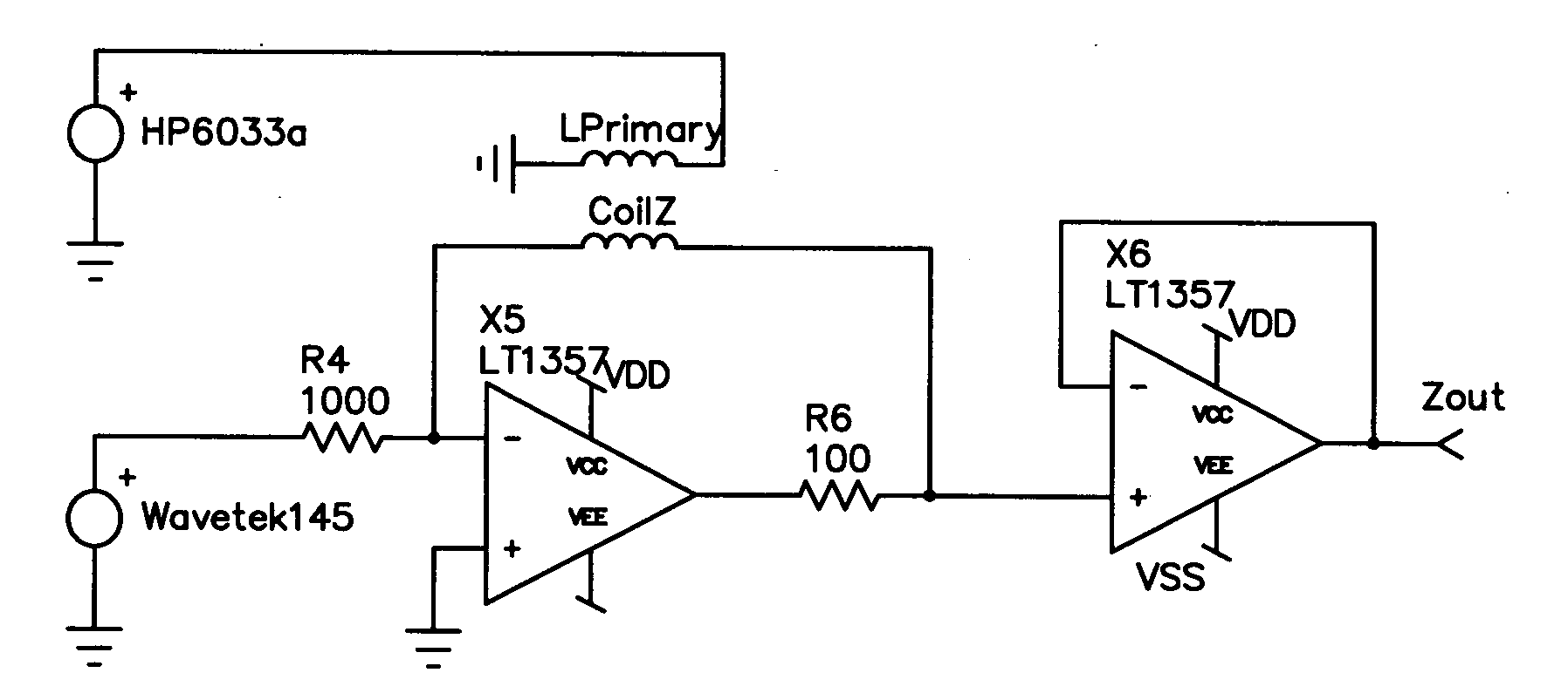
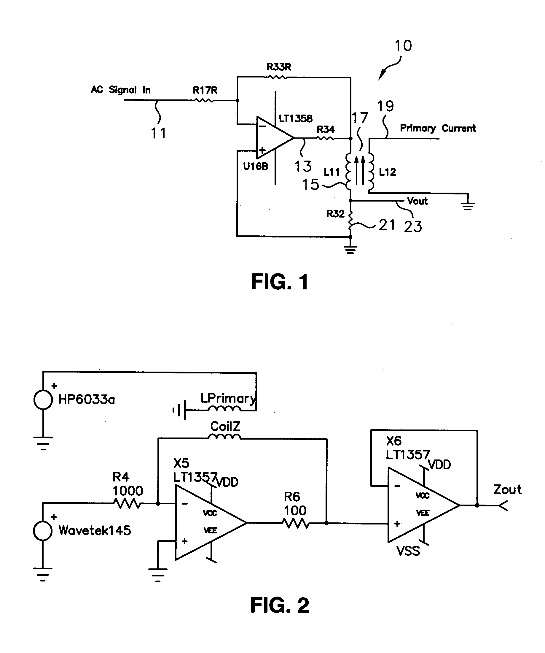
[0039] The principal components of the present invention are shown in FIG. 1 as a circuit diagram, 10 generally. An AC signal 11 is introduced through resistor R17, and received by amplifier LT 1358 to place an AC voltage 13 on coil 15. R 34 serves to protect the amplifier, by limiting the current drive of the amplifier U16B. Resistor R34 is placed within the op ...


PUM


Abstract

A sensor device comprising a magnetic material having nonlinear magnetic properties within an ambient magnetic flux. The device includes a signal conductor carrying a compound applied electric signal having two frequencies f1 and f2 and coupled to the magnetic material with the ambient magnetic flux to produce a resulting signal. A primary conductor carries a primary current coupled to the magnetic material having nonlinear magnetic properties to change the magnetic flux of the magnetic material and produce the resulting signal. The magnetic material may be open ended or in the shape of a toroid. In the latter case, the device further includes a primary conductor for carrying a primary current coupled to the magnetic material having nonlinear magnetic properties to change the magnetic flux of the magnetic material and produce the resulting signal. The primary and signal conductors are preferably configured as windings on the toroid. When the applied compound electrical signal having two frequencies is a voltage signal the resulting signal is current and when the signal is a current signal, the resulting signal is a voltage. An electrical circuit is used for detecting the resulting signal at frequencies f1=f2 or f1−f2 using a demodulation of the signal to thereby create a low frequency signal f3 related to the ambient magnetic flux magnitude and phase or polarity.

Description

[0001] This is a continuation-in-part of a commonly owned U.S. patent application having Ser. No. 11 / 066,788, filed Feb. 25, 2005, and incorporated herein by reference in its entirety.FIELD OF THE INVENTION [0002] The present invention relates to electric current sensors. More particularly, the invention relates to a sensor using a dual frequency detection scheme applied to the secondary sensing coil. BACKGROUND OF THE INVENTION [0003] There are a number of current sensors used in industrial applications. Example applications include motor control, uninterruptible power supplies, variable speed drives, welding power supplies and the like. There is a trend toward smaller size and lower cost for these current sensors. A number of designs use external magnetic fields, such as, for example, U.S. Pat. No. 3,461,387 which uses three or more coils and it is a device that detects external magnetic fields, not current. The use of a saturated magnetic core has been shown in U.S. Pat. No. 5,23...

Claims


Application Information

Patent Timeline
Patent Type & Authority Applications(United States)
IPC IPC(8): G01R15/20
CPCG01R15/183G01R15/185
Inventor SANDQUIST, DAVID A.PECZALSKI, ANDRZEJDEMMA, NICK
Owner HONEYWELL INT INC
Why Eureka
Try Eureka