Capacitor reliability for multiple-voltage power supply systems

Inactive Publication Date: 2006-08-31
GLOBALFOUNDRIES INC
View PDF7 Cites 2 Cited by
  • Summary
  • Abstract
  • Description
  • Claims
  • Application Information

AI Technical Summary

Benefits of technology

[0007] In an illustrative embodiment, a capacitor circuit comprises two capacitors, a voltage comparator, and a switch. Three voltage levels are provided: a power supply voltage, Vcc, a ground level, Vss, and a reference source voltage, Vref. Vref is placed at a voltage approximately equal to the maximum sustainable voltage at which the capacitors can achieve a desired reliability lifetime. The voltage comparator is operative to cause the switch to connect the two capacitors in p

Problems solved by technology

As dielectric layers are scaled, especially when scaled faster than the voltage or power supply level, premature punch-through, breakdown, and oth

Method used


Image

  • Capacitor reliability for multiple-voltage power supply systems
  • Capacitor reliability for multiple-voltage power supply systems
  • Capacitor reliability for multiple-voltage power supply systems

Examples


Embodiment Construction

[0014] The present invention will be illustrated below in conjunction with illustrative embodiments of capacitor circuits. It should be understood, however, that the invention is not limited to the particular circuitry arrangements of the illustrative embodiments. Moreover, in the illustrative embodiments, the capacitor circuit will be illustrated as a component of an integrated circuit. Nevertheless, the scope of this invention is intended to include a capacitor circuit formed of discrete device components mounted on, for example, a printed circuit board, substrate, etc. These and other possible modifications to the illustrative embodiments within the scope of this invention will be apparent to those skilled in the art.

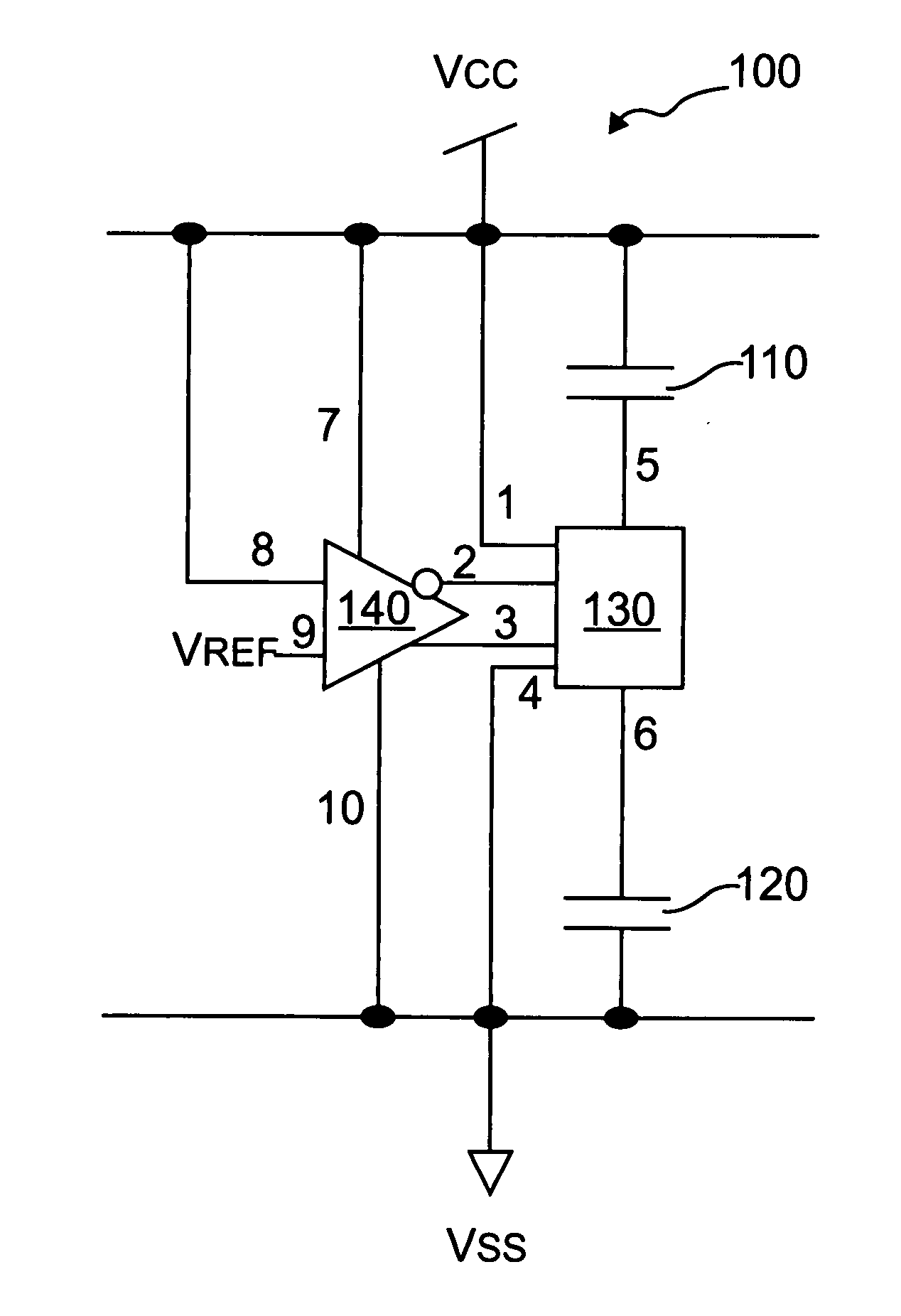
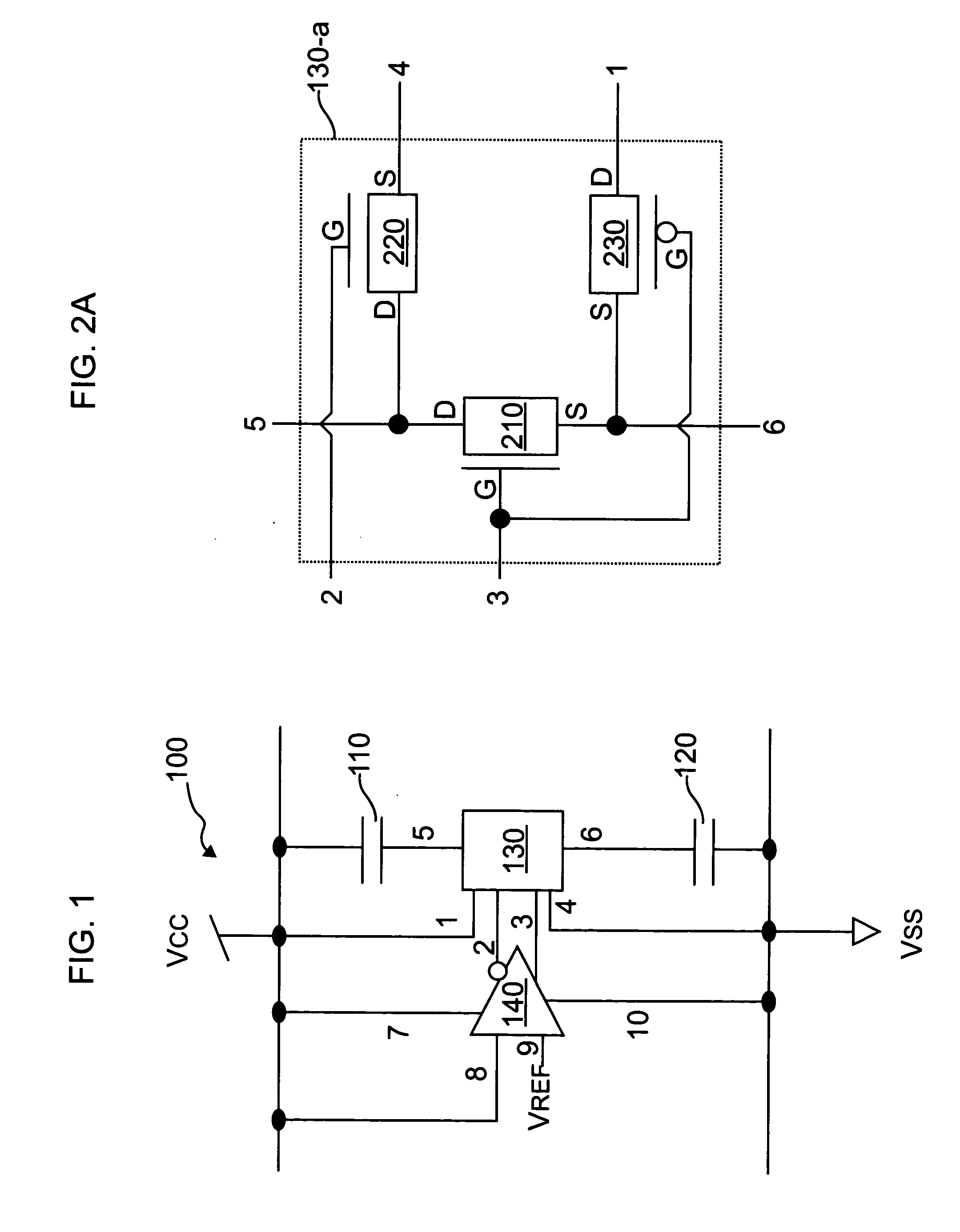
[0015]FIG. 1 is a schematic diagram depicting an exemplary capacitor circuit 100, formed in accordance with one embodiment of the present invention. The circuit 100 comprises two capacitors 110, 120, a switch 130, and a voltage comparator 140, or alternative voltage...


PUM


Abstract

A capacitor circuit having improved reliability includes at least first and second capacitors, a first terminal of the first capacitor connecting to a first source providing a first voltage, a first terminal of the second capacitor connecting to a second source providing a second voltage, the first voltage being greater than the second voltage. The capacitor further includes a voltage comparator having a first input for receiving a voltage representative of the first voltage, a second input for receiving a third voltage provided by a third source, and an output for generating a control signal. The control signal is a function of a difference between the voltage representative of the first voltage and the third voltage. A switch is connected to second terminals of the first and second capacitors. The switch is selectively operable in one of at least a first mode and a second mode in response to the control signal, wherein in the first mode the switch is operative to connect the first and second capacitors together in parallel, and in the second mode the switch is operative to connect the first and second capacitors together in series. The first mode is indicative of the voltage representative of the first voltage being less than or about equal to the third voltage, and the second mode is indicative of the voltage representative of the first voltage being greater than the third voltage.

Description

FIELD OF THE INVENTION [0001] This invention relates to capacitor circuits, and more specifically to capacitor circuits that are operative across a range of power supply voltages. BACKGROUND OF THE INVENTION [0002] Capacitors are widely used in semiconductor technology. They may be used, for example, for noise decoupling, for blocking direct current, and for charge storage in radio-frequency (RF) and analog applications. Semiconductor capacitors typically take the form of diffusion capacitors, trench capacitors, gate capacitors, and metal-insulator-metal (MIM) capacitors. Typically, these devices depend on an insulating layer, frequently silicon dioxide, to form the dielectric between the terminals of the capacitor. Like other layers in a semiconductor device, these dielectric layers are continuously scaled in order to make devices smaller, to increase performance, and to reduce cost of production. As dielectric layers are scaled, especially when scaled faster than the voltage or po...

Claims


Application Information

Patent Timeline
IPC IPC(8): H03K5/00
CPCH02M3/07
Inventor HSU, LOUIS L.JOSHI, RAJIV V.MANDELMAN, JACK ALLAN
Owner GLOBALFOUNDRIES INC
Why Eureka
Try Eureka