Gm-C Time Constant Tuning Circuit

Active Publication Date: 2006-08-31
VIA TECH INC
View PDF2 Cites 1 Cited by
  • Summary
  • Abstract
  • Description
  • Claims
  • Application Information

AI Technical Summary

Benefits of technology

[0007] The second conventional method of tuning is to copy a portion of conductance and capacitance of the Gm-C time constant of the filter utilizing a method of integration to obtain a ratio of conductance to capacitance and collocating feedback signals from other circuits to control the conductance value. For example, luri Mehr and David R. Welland published an article on “A CMOS Continuous-Time Gm-C Filter for PRML Read Channel Application at 150 Mb / s and Beyond⇄ in the IEEE Journal of Solid-state Circuit, they teach the utilization of an integrated circuit to obtain a plurality of ratios of conductance to capacitance similar to the ratio of conductance to capacitance of the variation filter such that the cut off frequency of the filter can be adjusted.

Problems solved by technology

The most common problems found in the Gm-C filter is that there is always a variation of 30% to 50% during the manufacturing of circuit components in an integrated circuit, and the variation of a capacitance is approximately 10% to 20%.
As a result, the accuracy of the bandwidth of the filter is affected.
Therefore, this approach is disadvantageous for a circuit that requires accurate frequency response.
These environmental changes cause a great offset to be generated such that the frequency response of the Gm-C filter cannot be amended immediately and the efficiency and accuracy of the circuit is therefore further affected.
However, the main disadvantage present in Khoury's five-level filter is that this type of circuit has a great surface area and therefore its power consumption is high; also the completion time taken for tuning is long and the tuning speed can be very slow as the Gm-C time constant can only be adjusted after the PLL is settled.
However, although the resulting tuning speed of the conventional integration method of FIG. 1 for tuning the Gm-C time constant of the tuning circuit 100 is much faster than utilizing the PLL to tune a circuit, there remain many inevitable defects still present given this approach.
Firstly, although the reference conductor 110 and the reference capacitor 120 each are only required to copy a portion of the original conductance and capacitor, the latter process is still complicated.

Method used


Image

  • Gm-C Time Constant Tuning Circuit
  • Gm-C Time Constant Tuning Circuit
  • Gm-C Time Constant Tuning Circuit

Examples


Embodiment Construction

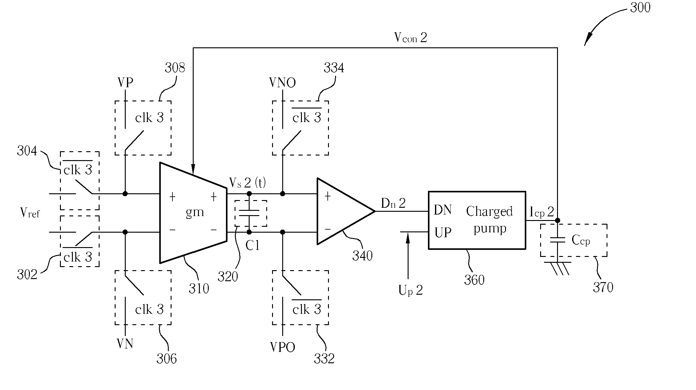
[0022] The present invention utilizes the integration method of the second conventional technology. This method is utilized to obtain the Gm-C time constant Gm / C of the Gm-C filter, but in the present invention the circuit has been simplified and the Gm-C time constant can be adjusted in continuous-time while the Gm-C filter is in an operating status thereby enabling the present invention to efficiently correct the offset generated by temperature and voltage changes in frequency response of the Gm-C filter when the circuit is operating.

[0023] Please refer to FIG. 3. FIG. 3 illustrates a diagram of a Gm-C time constant of a tuning circuit 300. A reference conductor 310 is a copied portion of a conductance Gm of the filter of the Gm-C time constant being tuned by the tuning circuit 300. It represents that the reference conductor 310 and the conductance Gm of the initial filter has the same characteristics, which causes the same degree in variation in manufacturing; and conductance of...


PUM


Abstract

A circuit including a Gm-C filter and an automatic Gm-C time constant tuning circuit is provided. The tuning circuit includes a reference conductor, a reference capacitor coupled to the reference conductor, a comparator generating signals according to a reference signal and the voltage signal at the output of the reference conductor, a feedback capacitor, and a charge pump charging and discharging a feedback capacitor according to the output of the comparator. The feedback capacitor provides a control voltage feedback to the tuning circuit and to the Gm-C filter for adjusting the conductance. Hence, in doing so, errors like manufacturing variation and offset can be prevented.

Description

CROSS REFERENCE TO RELATED APPLICATIONS [0001] This application claims the benefit of U.S. Provisional Application No. 60 / 593,846, filed Feb. 17, 2005, and included herein by reference.BACKGROUND OF THE INVENTION [0002] 1. Field of the Invention [0003] The present invention relates to a Gm-C filter of a semi-conductor component, and more particularly to an automatic tuning Gm-C filter of a Gm-C time constant tuning circuit of a semi-conductor component. [0004] 2. Description of the Prior Art [0005] A filter is required in most communication transmission application circuits. In general, a discrete-time filter can control a bandwidth more accurately, but the discrete-time filter is preferably more suited for a narrow bandwidth. A high frequency broadband circuit generally utilizes a continuous-time filter; and for the high frequency broadband circuit, a Gm-C filter will be a better choice, as its power consumption is low. The most common problems found in the Gm-C filter is that ther...

Claims


Application Information

Patent Timeline
IPC IPC(8): H03B1/00H03K5/00
CPCH03D13/004
Inventor CHEN, KUAN-TALIN, JOANNA
Owner VIA TECH INC
Why Eureka
Try Eureka