Mobile television receiver

a television receiver and mobile technology, applied in the field of system and method of reproducing a television signal, can solve the problems of encoder stopping the encoding operation, distortion of the reproduced audio and video signal, and distortion of the reproduced image on the display device and also in the audio signal, so as to reduce the effect of perceived image and audio quality

Inactive Publication Date: 2006-08-31
HARMAN BECKER AUTOMOTIVE SYST
View PDF5 Cites 14 Cited by
  • Summary
  • Abstract
  • Description
  • Claims
  • Application Information

AI Technical Summary

Benefits of technology

[0026] Although the system may be used for receiving a terrestrially broadcast television signal, it may also be employed for receiving television signals broadcast via satellite or received from a data storage device such as a DVD player. Television signal transmission paths may be error prone and the effect of errors to the perceived image and audio quality may be reduced by employing the invention.
[0027] The video frames of the received television signals may be encoded in accordance with one of the well-known international video coding standards, such as the family of MPEG coding standards. Video signals encoded by employing one of these digital coding standards can be transmitted in a simple manner together with digitally encoded audio signals over a communication link. The use of such standards ensures interoperability with existing reproduction devices, and in particular, those not being equipped with any error concealment technology. Even existing vehicles may benefit from the image and audio quality improvement when a vehicle, coach or train is equipped with a television receiver in accordance with this application.

Problems solved by technology

Such variations in signal strength may cause distortions in the reproduced image on the display device and also in the audio signal.
The occurrence of fading and a switching between different radio stations continuously interrupts the received television signal and causes distortions in the reproduced audio and video signal.
Such interruptions cause the encoder to stop the encoding operation.
A time consuming initialization procedure is required in the decoder of the reproduction device when the signal distortion is terminated and the transmission of encoded video and / or data is resumed.
Thus, the quality of the reproduced television signal is more greatly affected, since the actual period of the distortion is extended due to a required resynchronization procedure at the display device.
Consequently, a decoding and reproduction of new video information at the reproduction device cannot be started until the buffer has been filled again up to the predefined buffer level.
Typically, to reduce the impact of signal distortions on the perceived image quality, error concealment occurs at the display side, i.e., within the reproduction device.
Typically, the operations for transmitting the video information to the reproduction device, namely the encoding, transmission and decoding processing, abruptly break down if a distortion occurs in the received television signal.
During travel, the received television signal may be subjected to fading and frequent switching between different broadcast channels.
For example, short distortions may initiate the insertion of dummy data, distortions of an intermediate duration may initiate the insertion of a stored video frame, and longer lasting distortions may result in the insertion of a sequence of video or audio frames.
For example, a short disruption may cause an insertion of dummy data, while a longer distortion may cause the insertion of a pre-stored new sequence or a repetitive insertion thereof.

Method used


Image

  • Mobile television receiver
  • Mobile television receiver
  • Mobile television receiver

Examples


Embodiment Construction

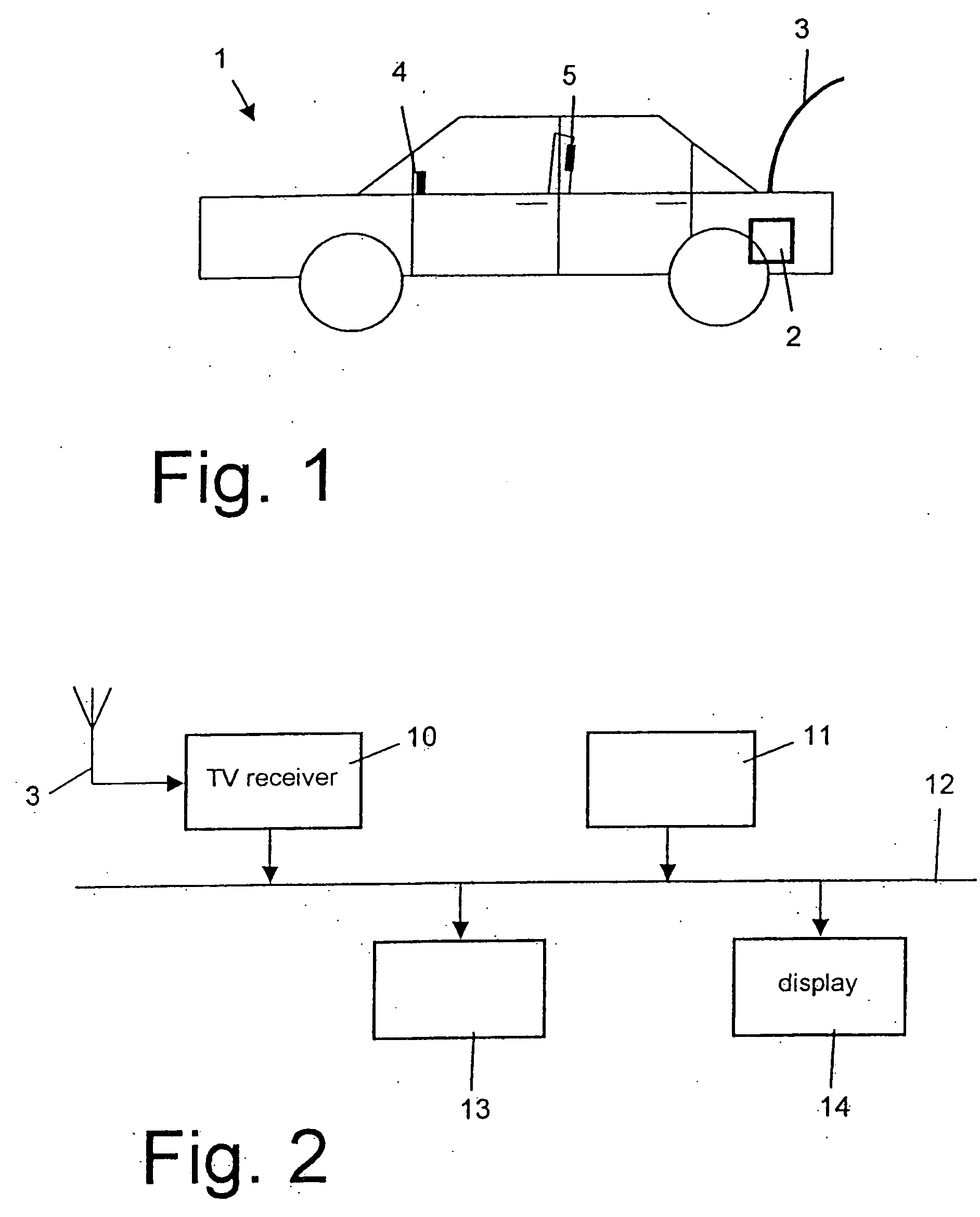
[0043] The invention is intended for use in mobile vehicles. As shown in FIG. 1, the different components of a mobile entertainment system, particularly of a mobile television system, may be distributed over distant locations within the vehicle. While the processing hardware may be mounted at the rear side of the vehicle, in proximity to an antenna 3, display devices 4 and 5 for the reproduction of video data may be mounted on the vehicle's dashboard, and / or behind the front seats for rear-seat passengers. The video signals to be displayed may be transmitted from the television receiver to the plurality of display devices 4 and 5 at locations distant therefrom. This situation particularly arises in coaches and trains where a single processing hardware provides a video signal to a plurality of display devices at the individual passenger seats. The video signal transmission, together with associated audio, is accomplished by employing a communication link coupling the display devices ...


PUM


Abstract

The invention relates to the reproduction of a television signal on a distant reproduction device. The received television signal is encoded and transmitted in a digital data format over a communication link to the reproduction device. The reproduction device decodes the received video information for display on a display screen. The invention is particularly intended for use in mobile vehicles, coaches and trains, where the signal strength of a received television signal during travel is continuously varying and signal distortions occur frequently. In order to reduce the effect of signal distortions on the perceived image and audio quality, the invention inserts a compressed pre-stored video or audio data into the data stream transmitted from the television receiver to the reproduction device upon detection of a television signal distortion. Thus, the decoding procedure at the display device can be maintained in spite of a received television signal of insufficient signal strength.

Description

PRIORITY CLAIM [0001] This application claims the benefit of priority from European Patent Application No. 04026829.4, filed Nov. 11, 2004, which is incorporated herein by reference in its entirety. BACKGROUND OF THE INVENTION [0002] 1. Technical Field [0003] The present invention relates to systems and methods for reproducing a television signal on a reproduction device, and in particular, to a mobile television receiver providing a television signal for reproduction to a reproduction device. [0004] 2. Related Art [0005] Automotive vehicles are increasingly being equipped with on-board television receivers. The television receivers may receive television programs broadcast terrestrially by one or more radio stations. The radio stations may be distributed such that, at each vehicle location within an area covered by a broadcast program, the vehicle can receive the program by at least one of the radio stations. Television receivers used in vehicles may select a particular channel for...

Claims


Application Information

Patent Timeline
Patent Type & Authority Applications(United States)
IPC IPC(8): H04N7/18H04N5/44H04N7/16H04N7/24H04N19/89
CPCH04N17/004H04N21/41422H04N21/414H04N21/442H04N21/431
Inventor TEICHNER, DETLEFLINK, HERMANN
Owner HARMAN BECKER AUTOMOTIVE SYST
Why Eureka
Try Eureka