Insulation for cryogenic tanks

a cryogenic tank and liquid storage tank technology, applied in the direction of domestic cooling devices, lighting and heating devices, container discharge methods, etc., can solve the problems of detrimental effect on the overall thermal insulation

Inactive Publication Date: 2006-09-07
GM GLOBAL TECH OPERATIONS LLC
View PDF0 Cites 46 Cited by
  • Summary
  • Abstract
  • Description
  • Claims
  • Application Information

AI Technical Summary

Benefits of technology

[0007] In another embodiment, the present invention provides a cryogenic storage system including an inner tank having a containment volume for storing a cryogenic fluid. An outer tank surrounds the inner tank and defines an insulation space having a pressure less than atmospheric pressure. At least two insulation layers are disposed in the insulation space surrounding the inner tank. The insulation layers are separated from one another by magnetic repulsion. Preferably, the insulation includes between about 20 to 40 layers, each about 50 to 90 microns in thickness, separated from one another by a magnetic field having a flux density of about 0.4 Tesla.

Problems solved by technology

As one of the primary sources of heat transfer, the spacers bridge the insulation that is present, and allow heat from the ambient environment to penetrate into the inner vessel, leading to detrimental effects on the overall thermal insulation.

Method used


Image

  • Insulation for cryogenic tanks
  • Insulation for cryogenic tanks
  • Insulation for cryogenic tanks

Examples


Embodiment Construction

[0016] The following description of the preferred embodiment(s) is merely exemplary in nature and is in no way intended to limit the invention, its application, or uses.

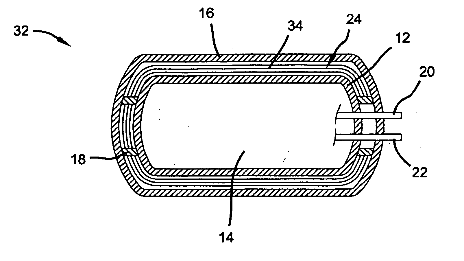
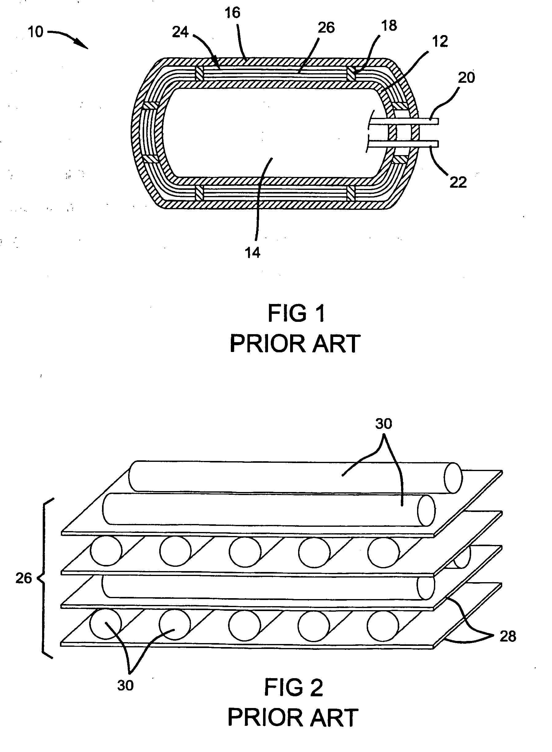
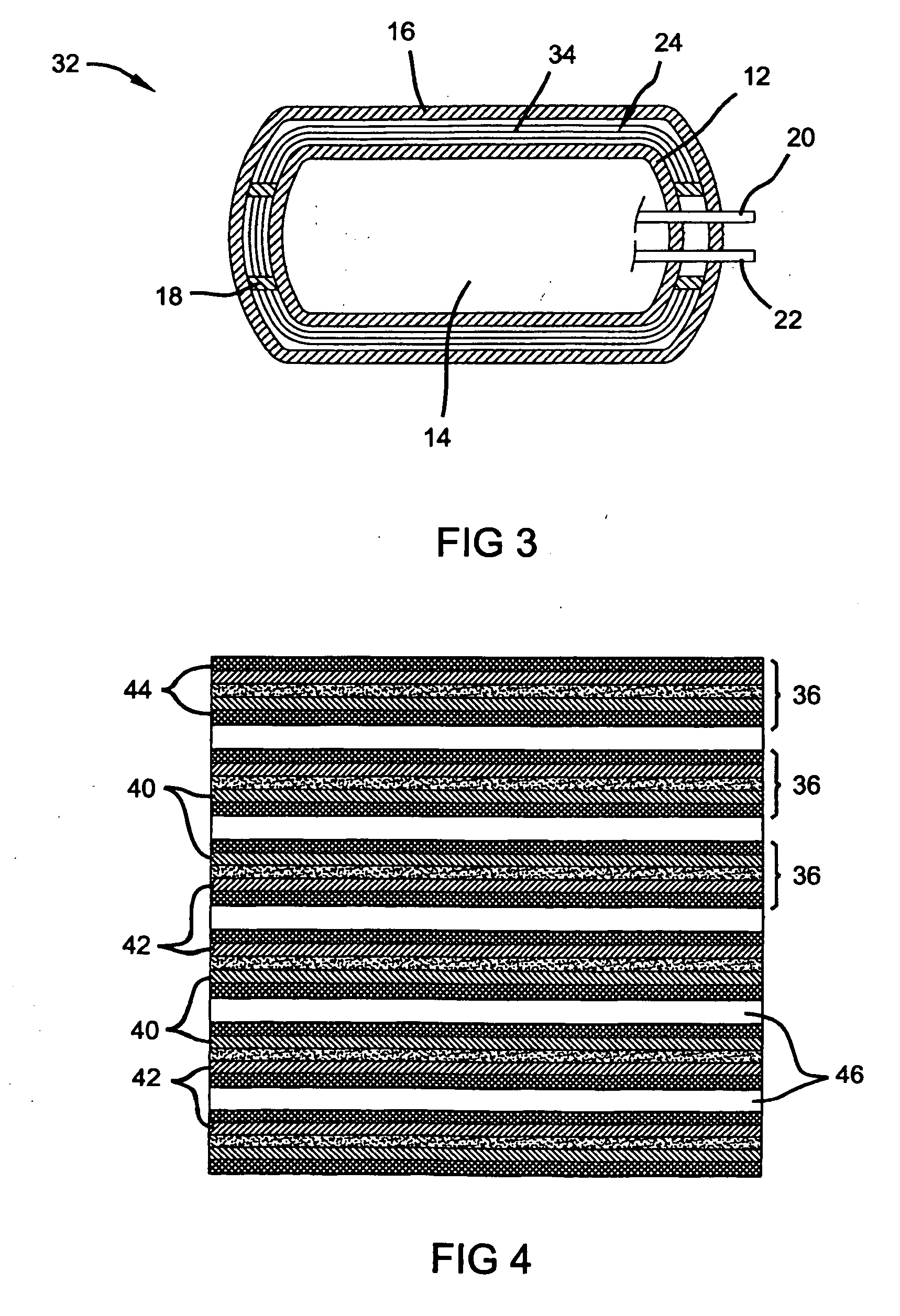
[0017]FIG. 1. is a cross-sectional view illustrating a typical design of a cryogenic storage tank 10. As illustrated, the cylindrical shaped storage tank 10 includes an inner vessel 12 having a containment volume 14 and surrounded by an outer vessel, or shell 16. The inner vessel 12 is generally separated from the shell 16 by a plurality of insulated cross supports 18 that prevent contact between the inner vessel 12 and the shell 16. One means of fluid communication into and out of the containment volume 14 is accomplished using an inlet port 20 and an outlet port 22, respectively. The cavity, or space 24 between the inner vessel 12 and the shell 16 is typically filled with a multi-layered thermal vacuum insulation 26 as is known in the art. The shell 16 operates to maintain a vacuum in the space 24 surrounding the ...


PUM


Abstract

A magnetic multi-layer insulation system for a cryogenic storage tank. The system includes multiple layers of insulation comprising a carrier support structure disposed between a first major surface of a magnetic material defining a north pole facing away from the carrier support structure, and a second and opposite major surface of a magnetic material defining a south pole facing away from the carrier support structure. A reflective surface, or metal foil, is disposed adjacent the magnetic poles to deflect radiation. The layers are repelled from one another without the use of spacers. In various embodiments, the magnetic material is a permanent magnet selected from the group consisting of Samarium-Cobalt, Alnico, Neodymium-Iron-Boron, an alloy of the Lanthanide group of elements, and mixtures and alloys thereof.

Description

FIELD OF THE INVENTION [0001] The present invention relates generally to cryogenic liquid storage tanks, and more particularly, to an improved cryogenic liquid storage tank insulation. BACKGROUND OF THE INVENTION [0002] Fuel cells have been proposed as a power source for electric vehicles and other applications. In proton exchange membrane (PEM) type fuel cells, hydrogen is supplied to the anode of the fuel cell and oxygen is supplied as the oxidant to the cathode. A common technique for storing large quantities of hydrogen is to cool and compress hydrogen via liquefaction techniques and store the liquid phase hydrogen in a cryogenic storage tank. Hydrogen gas liquefies at −253° C. and ambient pressure, and can be stored at about 70 g / L in the liquid phase. The amount of energy required to compress hydrogen gas into a liquid is very high, and currently may be as much as up to 40% of the energy obtained from using the gas as a fuel. Thus, it is advantageous to keep the liquid phase h...

Claims


Application Information

Patent Timeline
Patent Type & Authority Applications(United States)
IPC IPC(8): F17C13/00
CPCF17C3/04F17C3/08F17C2201/0104F17C2203/017F17C2203/0308F17C2203/0391F17C2203/0629F17C2209/232F17C2221/012F17C2223/0161F17C2223/033F17C2270/0168F17C2270/0184Y02E60/321F17C2203/014Y02E60/32
Inventor ROHWER, THORSTEN
Owner GM GLOBAL TECH OPERATIONS LLC
Why Eureka
Try Eureka