
Electromagnetic wave absorption complex, and method of producing the same

Inactive Publication Date: 2006-09-14
MIYAGAWA KASEI IND
View PDF8 Cites 21 Cited by
  • Summary
  • Abstract
  • Description
  • Claims
  • Application Information

AI Technical Summary

Benefits of technology

[0008] The present invention is made to solve the problems above. An object of the present invention is to provide a composite body for absorbing an electromagnetic wave of high strength, high heat resistance and high incombustibility, usable even outdoors and under the circumstances of high temperature and high humidity, and with electromagnetic wave absorbing performance excellent in high yield and productivity.
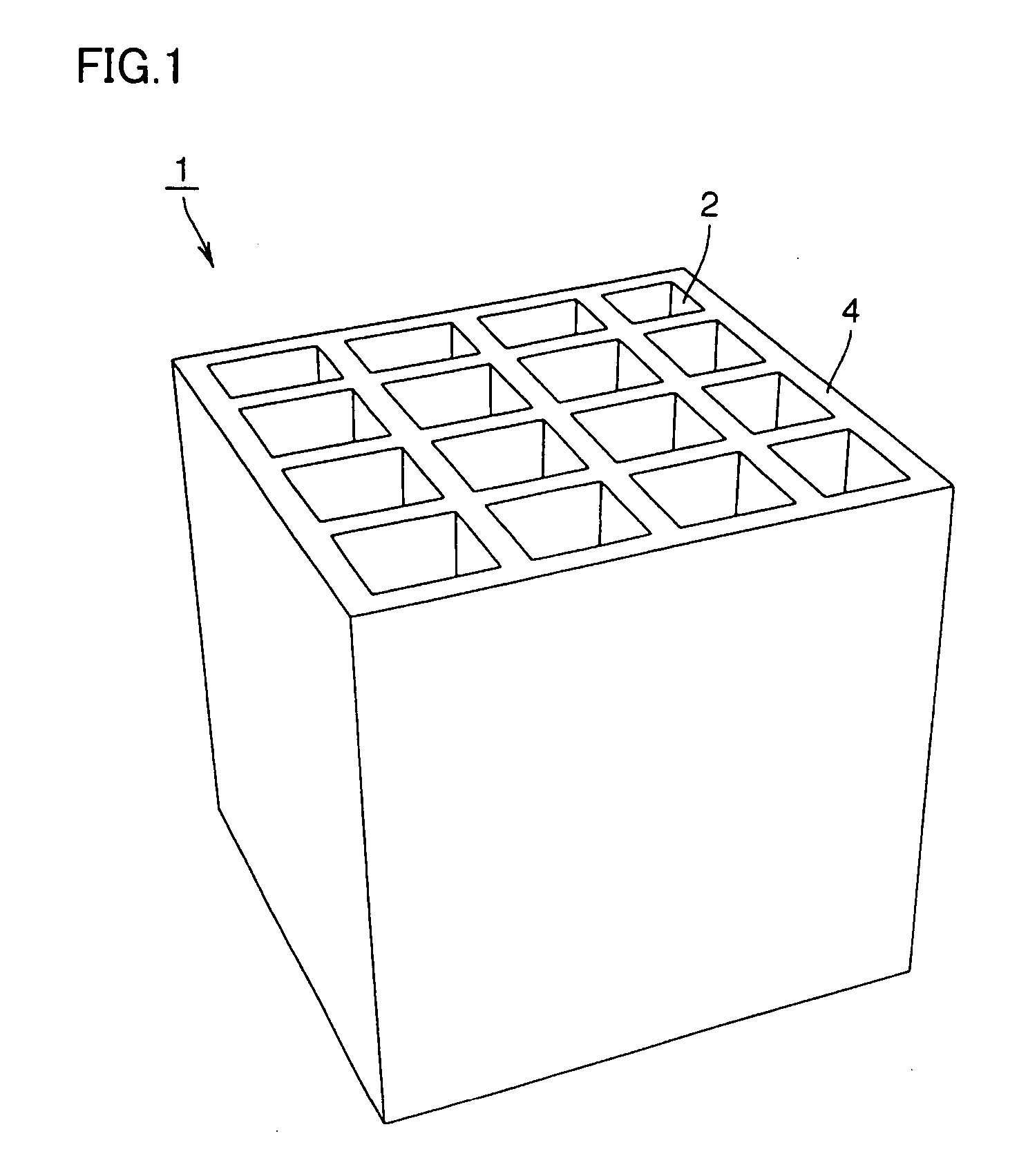
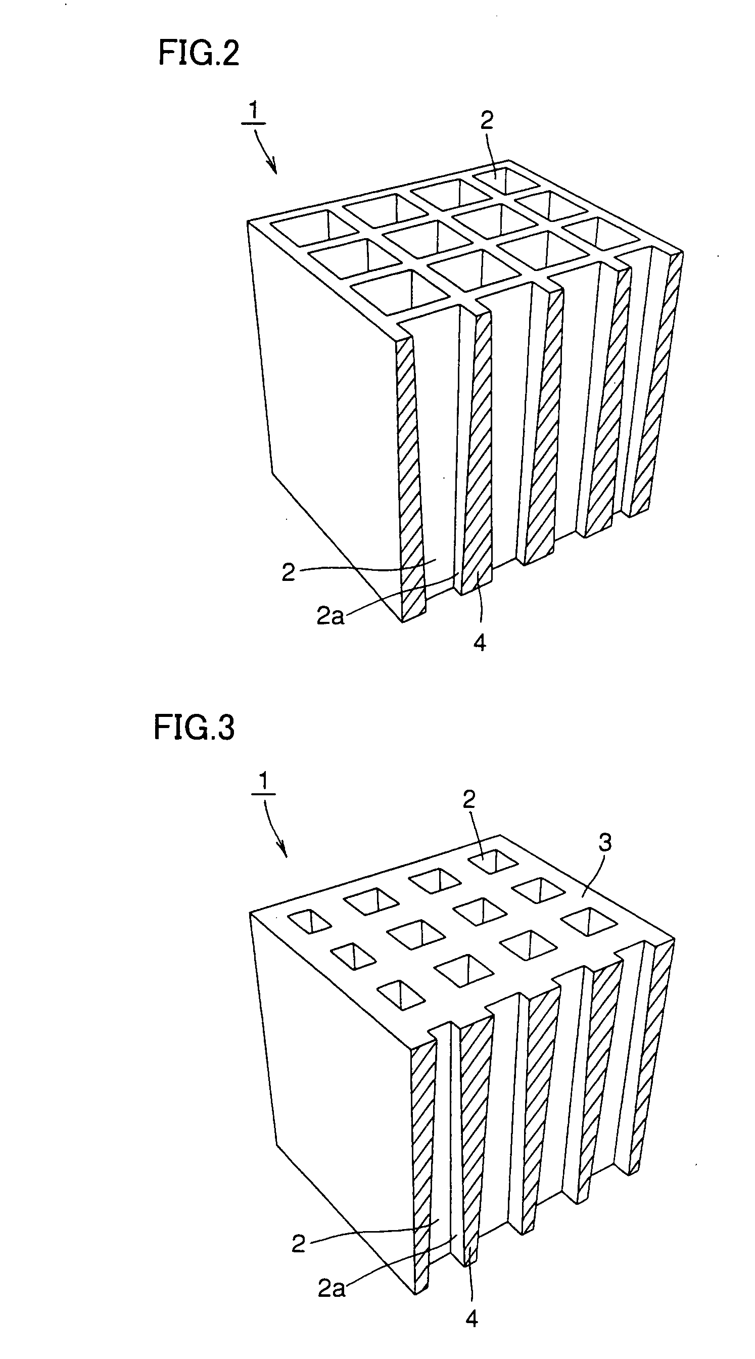
[0011] As described above, by setting the height of the unit cell from the bottom face to the top face to be approximately at least 1.2 times and approximately at most 10 times as large as the maximum width of the bore located at the top face of the unit cell, the composite body for absorbing an electromagnetic wave can attain improved electromagnetic wave absorbing performance and can be manufactured with high yields. Furthermore, by injection-molding the thermoplastic resin blended with the molding assistant and the kneading assistant, and further blended with approximately 20-60% by volume of the soft magnetic material powder, the steps of degreasing and sintering can be omitted, which makes it possible to mold a composite body for absorbing an electromagnetic wave with high yields and high precision even if the composite body has a relatively complex shape.
[0016] Furthermore, the soft magnetic material powder preferably has a mean particle diameter converted to spherical diameter of approximately 5-50 μm. This is because if the mean particle diameter converted to spherical diameter is approximately less than 5 μm, it becomes difficult to manufacture the soft magnetic material powder, which results in cost increase. If the mean particle diameter converted to spherical diameter exceeds approximately 50 μm, the ratio of the soft magnetic material powder blended into the thermoplastic resin is lowered, which results in lower electromagnetic wave absorbing performance.
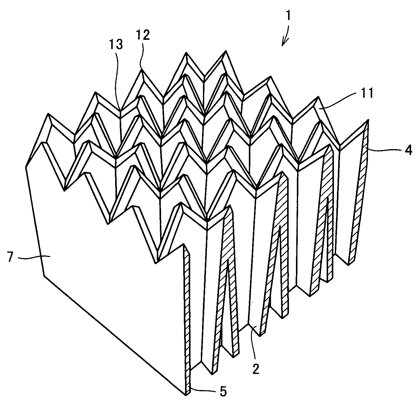
[0018] The inventors of the present invention have tested various shapes of composite bodies for absorbing an electromagnetic wave on their electromagnetic wave absorbing performance and found that it is possible to improve electromagnetic wave absorbing performance by providing concave and convex portions at the top face of the composite body for absorbing an electromagnetic wave, which has a bore of the shape above.
[0021] As such, the steps of degreasing and sintering are not performed after the step of injection molding, which causes no quenching crack and can improve yields. In addition, the process can also be simplified.
[0022] According to the present invention, after the thermoplastic resin blended with a specific material is injection-molded, a composite body for absorbing an electromagnetic wave can be formed without the steps of degreasing and sintering. Therefore, it is possible to obtain, with high yields, a composite body for absorbing an electromagnetic wave having a complex shape, having high strength and high heat resistance, and usable even outdoors and even under the circumstances of high temperature and high humidity. Moreover, since the height of the unit cell from the bottom face to the top face is set to be at least 1.2 times and at most 10 times as large as the maximum width of the bottom face of the unit cell, it is even possible to assure excellent electromagnetic wave absorbing performance. Additionally, it is also possible to obtain excellent electromagnetic wave absorbing performance by providing concave and convex portions at the top face of the composite body for absorbing an electromagnetic wave. Therefore, it is possible to obtain, with high yields, a composite body for absorbing an electromagnetic wave excellent in electromagnetic wave absorbing performance, heat resistance, and weather resistance.

Problems solved by technology

As the number of electronic devices has recently been increased, the individual devices are mutually interfered with electromagnetic waves emitted from the devices, which increasing the risk of their malfunction.
In addition, an electronic device may also malfunction due to an electromagnetic wave emitted from the device itself The effect of the electromagnetic wave emitted from the electronic device on a living body is also a matter of concern.
However, it is difficult to manufacture an electromagnetic wave absorber having a larger height.
Therefore, it is difficult to obtain, with high yields, an electromagnetic wave absorber excellent in electromagnetic wave absorbing performance.
Furthermore, the method described in the document above tends to cause quenching cracks after sintering, which contributes to the reduction in yield.
However, such an absorber has low strength and is highly flammable, resulting in poor durability.
Disadvantageously, such an absorber also has a water-absorbing property, which lowers its electromagnetic wave absorbing performance, and has low weather resistance, which makes the same unusable outdoors and under the circumstances of high temperature and high humidity.

Method used


Image

  • Electromagnetic wave absorption complex, and method of producing the same
  • Electromagnetic wave absorption complex, and method of producing the same
  • Electromagnetic wave absorption complex, and method of producing the same

Examples


example 1

[0079] A polypropylene resin was fed into a thermal and pressure kneader along with Permalloy (R) powder whose surface was subjected to coupling treatment to obtain affinity to the thermoplastic resin so that its mean particle diameter converted to spherical diameter was approximately 30-40 μm, and whose particles had a ratio (L / T) of maximum length (L) and thickness (T) of approximately 3-10, at the blending ratios shown in Table 1 below. The material above was heated to approximately 180-210° C. and kneaded for approximately 60 minutes under a pressure that could cause shearing force for kneading. The compound material that was kneaded uniformly and had an apparent viscosity of approximately 100-400 Pa·S was pelletized with a pelletizer. The pelletized material to be molded was fed into an injection molder to which a mold for injection molding was attached, to be heated and plasticized at approximately 180-230° C. The material was then injected into the mold at a high pressure of ...

example 2

[0080] By using a method similar to that of Example 1, it was possible to obtain composite bodies 3-9 for absorbing an electromagnetic wave with the blending ratios shown in Tables 2-4 below.

TABLE 2Blending Ratio (vol. %)electro-electro-electro-electro-magneticmagneticmagneticmagneticwavewavewavewaveabsorber 3absorber 4absorber 5absorber 6Permalloy (R)39.736.639.020.0powdermethylpentene33.745.944.466.8polymerpolybutene-120.212.610.28.6kneading assistant,6.44.96.44.6molding assistantand othersmean particle25.040.025.040.0diameter convertedto sphericaldiameter

[0081]

TABLE 3Blending Ratio (vol. %)electromagneticelectromagneticwave absorber 7wave absorber 8Permalloy (R) powder39.039.0methylpentene polymer44.554.6polypropylene10.10.0kneading assistant, molding6.46.4assistant and othersmean particle diameter30.030.0converted to spherical diameter

[0082]

TABLE 4Blending Ratio (vol. %)electromagneticwave absorber 9Permalloy (R) powder39.7nylon1255.7kneading assistant, molding assistant and o...

example 3

[0083] A methylpentene polymer resin and a polypropylene resin were fed into a thermal and pressure kneader along with gas-atomized spherical Permalloy (R) powder whose mean particle diameter converted to spherical diameter is approximately 37 μm, at the blending ratio shown in Table 5 below. The material above was heated to approximately 240-260° C. and kneaded for approximately 40 minutes under a pressure that could cause shearing force for kneading. The compound material that was uniformly kneaded and had a given viscosity was pelletized with a pelletizer. The pelletized material to be molded was fed into an injection molder to which a mold for injection molding was attached, to be heated and plasticized at approximately 200-260° C. The material was then injected into the mold at a high pressure of approximately 70 MPa-140 MPa and cooled for solidification. Thereafter, the compact was removed from the mold, and it was possible to obtain composite body 10 for absorbing an electrom...


PUM

PropertyMeasurementUnit
Diameteraaaaaaaaaa
Percent by volumeaaaaaaaaaa
Electromagnetic waveaaaaaaaaaa

Abstract

An electromagnetic wave absorber is formed by injection-molding a thermoplastic resin blended with approximately 20-60% by volume of soft magnetic material powder, and blended with a molding assistant and a kneading assistant. The electromagnetic wave absorber includes a unit cell having a bore extending from a top face to a bottom face. A portion of the bore located more adjacently to the bottom face than to the top face has a smaller cross-sectional area than the bore at the top face, and a height of the unit cell from the bottom face to the top face is approximately at least 1.2 times and approximately at most 10 times as large as the maximum width of the bore at the top face of the unit cell.

Description

TECHNICAL FIELD [0001] The present invention relates to a composite body for absorbing an electromagnetic wave, which serves to absorb a radio noise coming externally to prevent its effect, and a method of manufacturing the same. BACKGROUND ART [0002] As the number of electronic devices has recently been increased, the individual devices are mutually interfered with electromagnetic waves emitted from the devices, which increasing the risk of their malfunction. In addition, an electronic device may also malfunction due to an electromagnetic wave emitted from the device itself The effect of the electromagnetic wave emitted from the electronic device on a living body is also a matter of concern. [0003] Therefore, an electromagnetic wave absorber for absorbing a harmful electromagnetic wave with high efficiency has increasingly been developed in recent years, and various shapes of the electromagnetic wave absorber and methods of manufacturing the same have been proposed. [0004] For exam...

Claims


Application Information

Patent Timeline
IPC IPC(8): H01Q17/00H05K9/00
CPCH05K9/0083H05K9/00
Inventor NODA, KENICHIKATO, YASUMASAKITAMURA, HARUOOGAWA, MASAO
Owner MIYAGAWA KASEI IND
Learn More