Wafer holding mechanism

a holding mechanism and wafer technology, applied in auxillary welding devices, printing, instruments, etc., can solve the problems of destroying the chuck table, affecting the chuck, and affecting the chuck

Active Publication Date: 2006-09-14
DISCO CORP
View PDF5 Cites 20 Cited by
  • Summary
  • Abstract
  • Description
  • Claims
  • Application Information

AI Technical Summary

Benefits of technology

[0009] Accordingly, it is an object of the present invention to solve the above-described problems of the conventional art by preventing the holding table that holds a wafer from heating up when a laser is used to process the wafer.

Problems solved by technology

However, it is difficult for the cutting blade to dice the wafer into separate devices when, for example, the wafer is formed of a material high on the Moh's hardness scale, such as a sapphire substrate.
However, even with the use of a laser of a wavelength with a high rate of absorption by the wafer, most of the light permeates the wafer and reaches a chuck table that suctionally holds the wafer in place, damaging the chuck table.
Moreover, where protective tape is affixed to the surface of the wafer that is held to the chuck table, the chuck table is heated by the laser beam, which in turn heats the protective tape and causes it to melt, which not only makes it difficult to transport the wafer from the chuck table but also causes the melted protective tape to adhere to the chuck table, dirtying the chuck table and adversely affecting future use thereof.
At the same time, attempting to make the chuck table out of a material with a high rate of absorption of the laser beam depending on the wavelength of the laser makes it difficult to open fine holes in such a material that are used to transmit a suction force to the wafer.

Method used


Image

  • Wafer holding mechanism
  • Wafer holding mechanism
  • Wafer holding mechanism

Examples


Embodiment Construction

[0039] A detailed description will now be given of preferred embodiments of the present invention, with reference to the accompanying drawings.

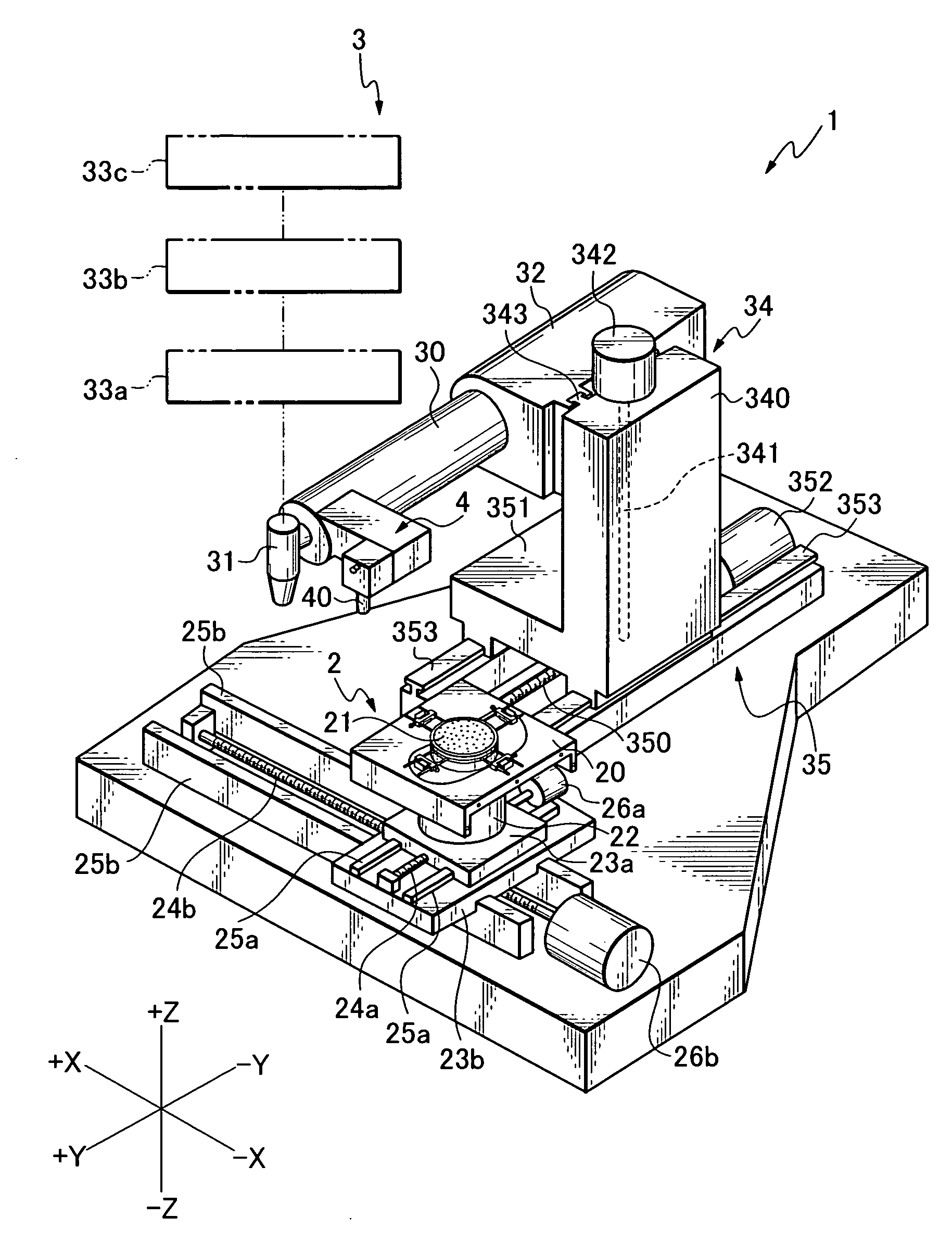
[0040] As a processing apparatus to which a wafer holding mechanism according to the present invention is applied, there is, for example, a laser processing apparatus 1 shown in FIG. 1. The laser processing apparatus 1 cuts through and opens holes in a wafer or other target object to be processed, and comprises a retention means 2 that holds the target object and a processing means 3 that cuts through and opens holes in the target object with a laser beam.

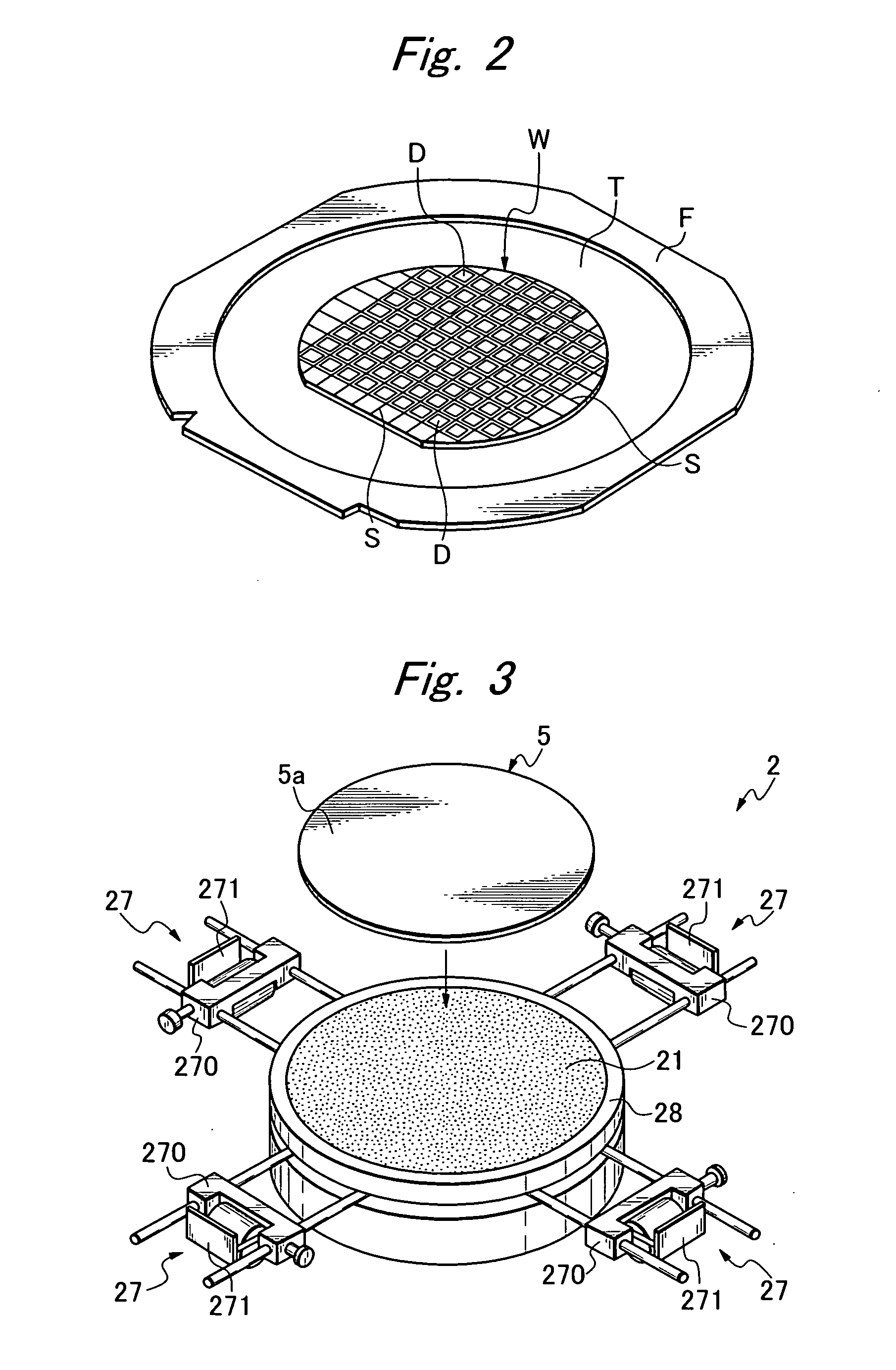
[0041] The retention means 2 has a suction unit 21 that is rotatably supported on a support plate 20, with the suction unit 21 coupled to a drive source 22 so as to be rotatable. The drive source 22 is fixedly mounted on a movable base 23a. An internal nut of the movable base 23a engages a ball screw 24a disposed along the Y-axis so that the movable base 23a is slidable along a pair of gui...


PUM

PropertyMeasurementUnit
widthaaaaaaaaaa
widthaaaaaaaaaa
suction forceaaaaaaaaaa

Abstract

To prevent heating of a holding table that holds a wafer when using a laser beam to process a wafer, a wafer holding mechanism has a wafer holder having a holding surface that holds a wafer and a suction part formed on an outer peripheral side of the wafer holder, with the wafer held to the holding surface by a suction force transmitted to the holding surface from the suction part through an outer peripheral edge part of the wafer holder. The wafer can be held in place with suction without forming fine holes that penetrate the wafer holder from a front surface thereof to a back surface thereof, and therefore a material of good permeability and dispersibility with respect to the wavelength of the laser light can be selected for the wafer holder.

Description

BACKGROUND OF THE INVENTION [0001] 1. Field of the Invention [0002] The present invention relates to a holding mechanism for holding a wafer that is a target object to be processed. [0003] 2. Related Art [0004] Conventionally, a wafer divided along predicted separation lines into individual devices such as ICs, LSIs and the like is cut by a cutting blade along the separation lines so that the wafer separates into individual devices. However, it is difficult for the cutting blade to dice the wafer into separate devices when, for example, the wafer is formed of a material high on the Moh's hardness scale, such as a sapphire substrate. [0005] Accordingly, recently, a technique involving directing a pulse laser onto the separation lines, forming grooves in such separation lines and separating the wafer into the individual devices has been proposed (for example, JP-A-10-305420). [0006] However, even with the use of a laser of a wavelength with a high rate of absorption by the wafer, most...

Claims


Application Information

Patent Timeline
Patent Type & Authority Applications(United States)
IPC IPC(8): G03B27/58
CPCB23K26/4075B23K37/0408B23K2201/40B25B11/005B28D5/0094G03F7/707H01L21/6838B23K26/40B23K2101/40B23K2103/50
Inventor OHMIYA, NAOKIGENDA, SATOSHITAKEDA, NOBORUTAKEYAMA, KOICHIMORISHIGE, YUKIOMORIKAZU, HIROSHINOMURA, HIROSHI
Owner DISCO CORP
Why Eureka
Try Eureka