Low cost fiber-optic gage and associated multi-channel all-optical data collecting system

a fiber-optic gage and all-optic technology, applied in the field of physical phenomena, can solve the problems of inability to reliably measure the phenomenon, the cost and complexity of the electronic and optical systems required to implement the fiber-optic gage were prohibitively high for most applications, and limited their application in certain fields, so as to improve the reliability and stability of the measurement, and extend the light attenuation range.

Inactive Publication Date: 2006-09-14
IVTSENKOV GENNADII
View PDF21 Cites 23 Cited by
  • Summary
  • Abstract
  • Description
  • Claims
  • Application Information

AI Technical Summary

Benefits of technology

[0047] It is an object of the present invention to provide a low cost, simplified and insensitive to ambient conditions fiber-optic gage for measuring physical phenomena, such as pressure, temperature and force, which utilizes effect of light attenuation in a single-mode optic fiber, induced by the specific bending of the fiber. Another object of the present invention is to provide a multi-channel fiber-optical data collecting system simultaneously or in time sequences gathering information from a number of said gages. SUMMARY OF THE INVENTION
[0053] Because of relatively high linear movement of the fiber, which is utilized in the bending devices of the present invention, possible influence of ambient conditions, such as temperature, vibration, etc. is negligible. This approach allow eliminating the second optic fiber—a reference one—that is essential for the gages based on mentioned above principles to compensate ambient condition variations. Thus, this invention allows drastically simplifying design of the gage and associated data collecting system, therefore, increasing reliability and minimizing the cost of the system.

Problems solved by technology

This optical sensor technology has overcome many of the inherent disadvantages of resistance strain gages and its electrical transmission networks, including long-term measurement drift, sensitivity to electromagnetic interference, and dangers from electrical power requirements, which have limited their application in certain fields, such as fire and explosion hazardous environments.
Within the past two decades, a number of manufacturers have attempted to exploit the fiber-optic sensor technology, with limited results.
The costs and complexity associated with the electronic and optical systems required to implement the fiber-optic gages were prohibitively high for most applications.
Also, affect of ambient conditions, such as temperature, vibration, etc. on gage characteristics made these gages unreliable.
So, it is useless for measurement of stationary parameters (varying with low frequency), but can be utilized in microphones, hydrophones, etc.
The review of the existed fiber-optic strain sensors, its principles and designs reveals that the sensors mentioned above have some disadvantages, such as high cost and complexity of measuring equipment.
In some cases, the data collecting systems utilizing these sensors have problems with the measurement instability, temperature and polarization sensitivity (especially, interferometer-based sensors).
Moreover, measuring system implementing fiber-optic strain sensors based on Bragg grating technology requires complicated multi-line single-mode light source that has to provide large number of spectral lines, or multi-line wavelength scanning light source.
In this case, when such multimode fiber—the sensing element of the proposed devices—is bent, the number of modes of the light running in the fiber declines, so total transparency of the fiber declines too.
Research of the possibility of optic fiber utilization for physical phenomena sensing reveals that multimode fiber are not suitable for such measurements, because they do not provide stable and repeatable reading.
This disadvantage is caused by the multimode mechanism of light propagation in step-index multimode fibers, where the number of modes can reach up to a few hundred ones and each mode has its individual losses.
Also, utilization of multi-mode fiber-optic sensors requires multimode fiber-optical lines collecting data from the sensors that can not be longer than a few hundred meters that drastically restricts applicability of these sensors for remote monitoring.
Because of the problems mentioned above, the fiber-optic sensors based on this effect can not be successfully utilized for mass application in monitoring systems.
There is another problem significantly affecting characteristics of the fiber-optic sensors described in the mentioned patents.
Therefore, the shape of the fiber loop formed by such way is unstable and highly depends on ambient conditions, such as temperature (changing flexure of the fiber), etc.
Moreover, in such sensors the maximal response is produced by intermediate parts of the bent fiber—the parts between end fibers and the loop, which are less controllable.
As the result, despite of variety of patented fiber-optic micro-bending sensors, most of them have not found application in practice (other than for alarm mode or tactile sensing) due to problems associated with erratic response, tolerances of the deformers and mechanical fatiguing of the fiber that especially appears at high temperature condition because of viscoelastic deformation of the glass (G. Scott Glaesemann, et al “Analysis of optical fiber failures under bending and high power”, Reliability of Optical Fiber Components, Devices, Systems, and Networks II, Vol. 5465; pp.
Such bending produces high attenuation, but it is unstable, affected by small unwanted displacements and can cause the fiber failure.
These parts provides high attenuation, but they are unstable, affected by small unwanted displacements and can cause the fiber failure.
The signal of such wavelength has unstable characteristics, can not be properly transmitted via a conventional single-mode line; and, as result, it can not be used as a reference one.
It seems that the idea and the method proposed by the author of U.S. Pat. No. 4,727,254 can not properly work in the devices and data collecting systems based on bending of single-mode optic fiber.
Such range is, obviously, not enough for reliable measurements, because any deviation of parameters of light source and optical line, which can achieve about 0.2-0.3 dB drastically diminish accuracy of such measurements.

Method used


Image

  • Low cost fiber-optic gage and associated multi-channel all-optical data collecting system
  • Low cost fiber-optic gage and associated multi-channel all-optical data collecting system
  • Low cost fiber-optic gage and associated multi-channel all-optical data collecting system

Examples


Embodiment Construction

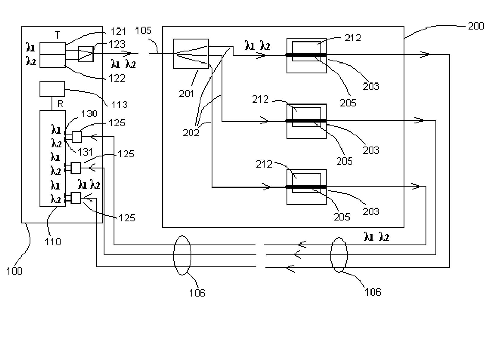
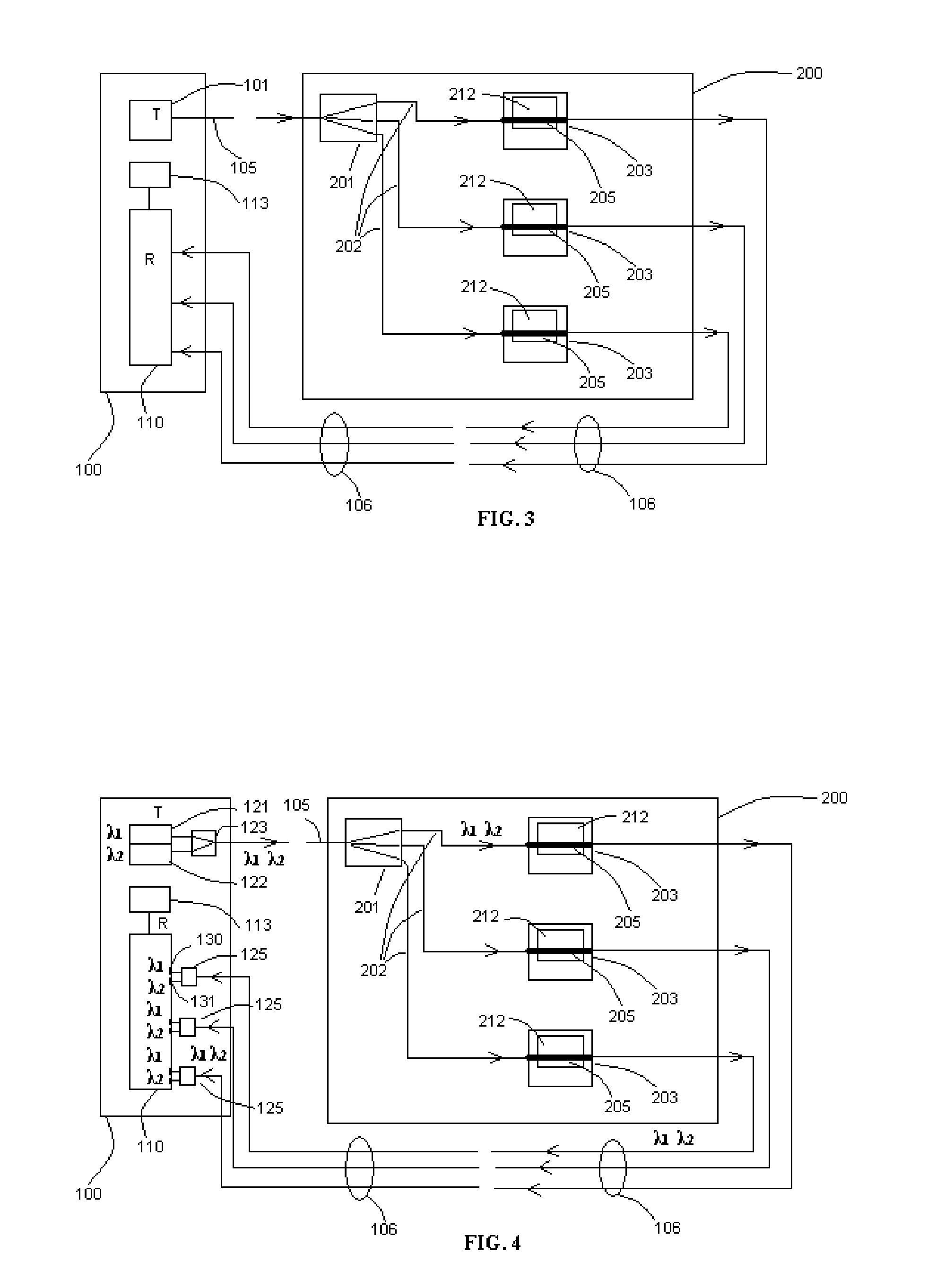
[0056] The scheme of the invention—multi-channel all-optical data collecting system gathering information from a number of fiber-optic gages—is depicted in FIG. 3. An electro-optical module 100 comprises a transmitting unit 101, receiving unit 110 and processing unit 113. The transmitting unit 101 of the electro-optical module 100 contains a single-mode fiber-optic source of light, such as a 1310-nm (or 1550 nm) laser diode developed for telecommunication lines. The light source of the unit 101 is optically coupled to an input single-mode fiber-optical line 105, and the light entering the fiber-optical line 105 propagates along that line until it reaches the sensing module 200. In that module, the light passes through a single-mode splitter 201 with number of outputs equal to the number of gages 203. Each output of splitter 201 is optically coupled to delivering single-mode fiber-optical lines 202 transmitting the light to each individual gage. Therefore, the light further propagate...


PUM


Abstract

Simplified and insensitive to ambient condition fiber-optic gage and associated multi-channel data collecting system capable of all-optical measurements of a physical phenomenon, such as gas and liquid pressure, temperature, structural movement and force without fire and explosion hazards associated with conventional strain gage technologies, such as resistance foil strain gages. The gage houses a sensitive element—a length of single-mode optic fiber and a bending device converting the measured phenomenon into specific bending of the optic fiber. Here, amplitude of a single-mode light passing the gage experiences variation under this specific mechanical bending applied to the sensitive element of the gage. A multi-channel time-division multiplexing data collecting system that includes another object of this invention—a single-mode fiber-optic switch. The invention may be embodied to measure any phenomenon that can be converted into the bending of a single-mode optical fiber.

Description

FIELD OF THE INVENTION [0001] The present invention relates to the measurement of physical phenomena, such as pressure, temperature, structural movement and force by fiber-optic gage utilizing the effect of light attenuation under bending of an optic fiber. More particularly, the invention pertains to utilize the specific bending of single-mode optical fiber-radial stretching of circular coil of optic fiber and winding the fiber around fixed-radius shaft with controllable arc angle of the winding. The present invention also relates to associated multi-channel single-mode fiber-optical data collecting system and its elements, such as a fiber-optic switch, which allows all-optical remote monitoring. BACKGROUND OF THE INVENTION [0002] This application is the corresponding non-provisional one related to the provisional application No. 60 / 594,064 filed Mar. 8, 2005. [0003] Fiber-optic sensors successfully substitute now conventional resistance strain gages that have been the most widely ...

Claims


Application Information

Patent Timeline
Patent Type & Authority Applications(United States)
IPC IPC(8): G02B6/00G02B6/42G01J1/04G02B6/26
CPCG01D5/35383G01K11/32G02B6/266G02B6/35G02B6/3548
Inventor IVTSENKOV, GENNADII
Owner IVTSENKOV GENNADII
Why Eureka
Try Eureka