Cold spray process for seal applications

a technology of cold spraying and sealing, applied in the direction of liquid fuel engines, machines/engines, mechanical equipment, etc., can solve the problems of reducing sealing efficiency, metallic debris that can damage downstream airfoils, and metal strips that tend to mushroom or flatten

Active Publication Date: 2006-09-21
SIEMENS ENERGY INC
View PDF22 Cites 34 Cited by
  • Summary
  • Abstract
  • Description
  • Claims
  • Application Information

AI Technical Summary

Problems solved by technology

The metal strips tend to mushroom or flatten due to rubbing.
This produces rounded seal surfaces that reduce sealing efficiency.
This rubbing may also produce metallic debr

Method used


Image

  • Cold spray process for seal applications
  • Cold spray process for seal applications
  • Cold spray process for seal applications

Examples


example 1

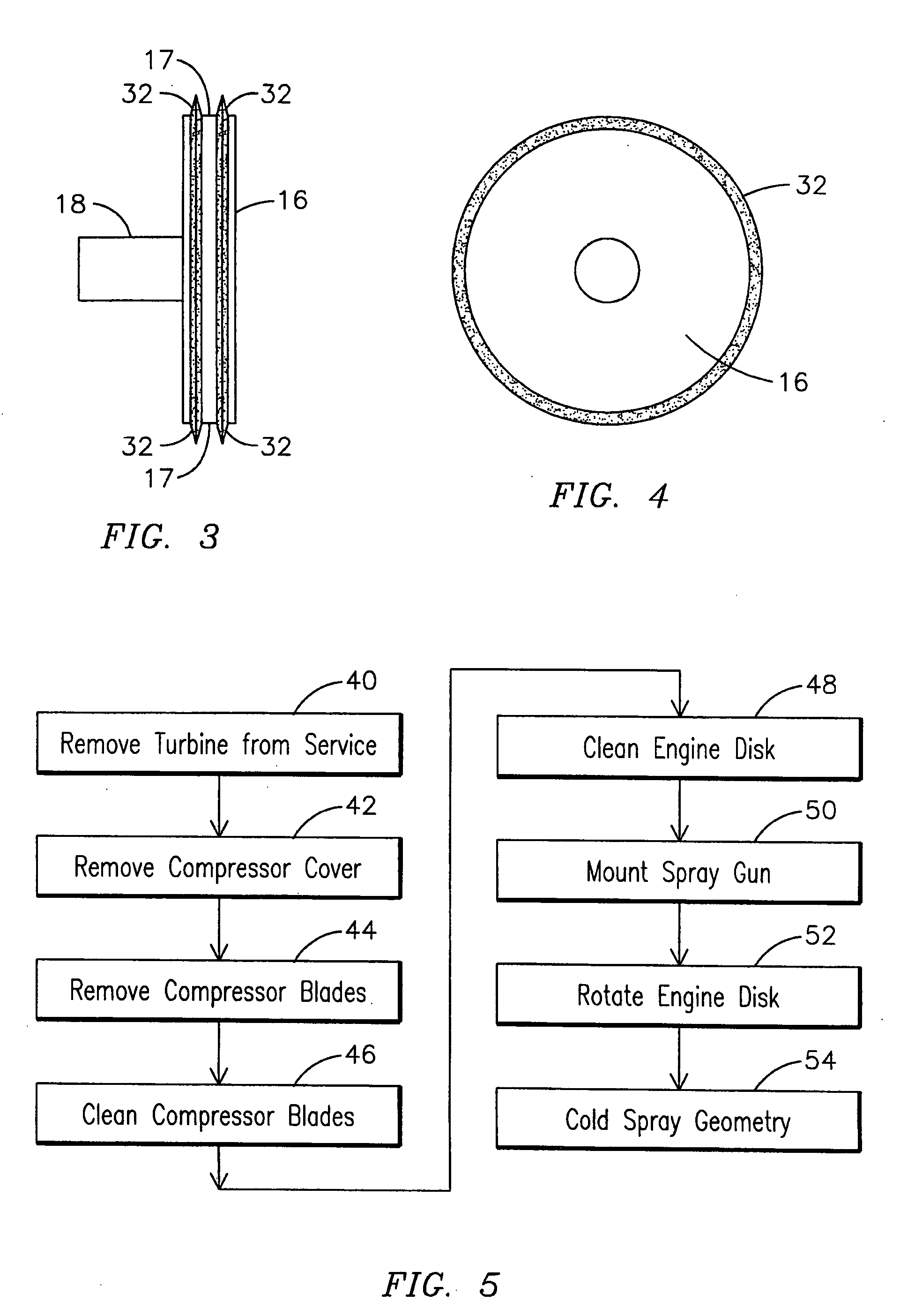
[0026] In this example, parallel ridges, such as ones used to form ridges 32 shown in FIG. 3, of 316L stainless steel were sprayed onto a flat plate of 4340 steel using a cold-spray technique. The spray conditions were varied slightly between ridges and the efficacy of each spray condition was evaluated by later cutup and metallography of the sprayed ridges. The spray conditions used for each ridge are listed in Table 1. A commercial 316L stainless steel powder with a sieve size predominantly between 11 and 38 microns was used for all spray trials.

TABLE 1Cold Spray Conditions†Measured ParticleGun Traverse RateNumberVelocityRidge #(meters / minute)of Passes(meters / second)118.7150610-7402 9.5100610-740

†Common spray conditions were as follows:

Nitrogen pressure: 3.25 MPa

Nitrogen temperature: 550° C.

Nitrogen flow rate: 85 cubic meters / hour

Gun nozzle exit diameter: 6.4 mm

[0027] The gun was translated 150 microns laterally after each subsequent pass to deposit the next pass (i.e., the...

example 2

[0028] In this example, two concentric ridges, such as ones used to form ridges 32 in FIG. 3, of 316L stainless steel were sprayed onto a 15 cm diameter disk of 4340 steel using a cold-spray technique. The spray conditions were varied slightly for each ridge, with the conditions used listed in Table 2. A commercial 316L stainless steel powder with a sieve size predominantly between 11 and 38 microns was used for all spray trials.

TABLE 2Cold Spray Conditions†Measured ParticleGun Traverse RateNumberVelocityRidge #(meters / minute)of Passes(meters / second)144450580-730231300580-730

†Common spray conditions were as follows:

Nitrogen pressure: 3.25 MPa

Nitrogen temperature: 550° C.

Nitrogen flow rate: 85 cubic meters / hour

Gun nozzle exit diameter: 6.4 mm

[0029] The gun was translated 150 microns laterally after each subsequent pass to deposit the next pass (i.e., the step size was 150 microns). No cutup or metallography was done on the ridges deposited onto the disk, but the cold-sprayed t...


PUM

PropertyMeasurementUnit
Widthaaaaaaaaaa
Widthaaaaaaaaaa
Temperatureaaaaaaaaaa

Abstract

A method of forming an interstage seal including removing a diaphragm seal box (14) from a gas turbine compressor assembly (10) and removing a labyrinth sealing member (12) from the diaphragm seal box (14). An abradable material layer (34) may be deposited on the diaphragm seal box (14). A spray gun may be mounted in relation to an engine disk (16) of the gas turbine compressor assembly (10) for cold-spraying a quantity of particles toward the engine disk (16). The particles may be sprayed at a velocity sufficiently high to cause at least a portion of the quantity of particles to adhere to the engine disk (16). The spray gun may be controlled to deposit a quantity of particles on the compressor disk (16) to form a geometry (32) that will abrade the abradable material layer (34) during operation of the gas turbine compressor assembly (10). The geometry (32) abrading the abradable material layer (34) forms an interstage seal. Rotation of the engine disk (16) within the gas turbine compressor assembly (10) may be controlled during the step of controlling the spray gun. The diaphragm seal box (14) may be reinstalled within the gas turbine compressor assembly (10) so that the geometry (32) aligns with the abradable material layer (34).

Description

FIELD OF THE INVENTION [0001] This invention relates generally to the field of materials technologies, and more specifically to the field of retrofitting a turbine assembly to form a seal between a rotating and a stationary component by applying material to the rotating component using a cold spray technique. BACKGROUND OF THE INVENTION [0002] Certain combustion turbine engines such as the W501F / G engines manufactured by the assignee of the present invention use metal labyrinth seal strips affixed to and extending from a stationary diaphragm carrier. The metal strips rub against rotating compressor disks to reduce interstage leakage. The metal strips tend to mushroom or flatten due to rubbing. This produces rounded seal surfaces that reduce sealing efficiency. This rubbing may also produce metallic debris that can damage downstream airfoils. To avoid this problem, clearances between the metal strips and compressor disks may be increased. However, this also reduces the interstage sea...

Claims


Application Information

Patent Timeline
IPC IPC(8): B23P6/00
CPCB23P6/007F01D5/005F01D11/02F05D2230/90Y10T29/49238F05D2230/80Y10T29/49231Y10T29/49318Y10T29/49236F05D2230/30
Inventor ALLEN, DAVID B.SUBRAMANIAN, RAMESH
Owner SIEMENS ENERGY INC
Why Eureka
Try Eureka