Control apparatus for internal combustion engine

Inactive Publication Date: 2006-09-21
TOYOTA JIDOSHA KK
View PDF8 Cites 24 Cited by
  • Summary
  • Abstract
  • Description
  • Claims
  • Application Information

AI Technical Summary

Benefits of technology

[0011] In view of the foregoing, an object of the present invention is to provide a control apparatus that can efficiently detect injector disconnection failure, including identification of the injector with disconnection fai

Problems solved by technology

In the case where current is not applied to the solenoid coil when a fuel injection signal is generated due to occurrence of disconnection failure at the injector, fuel injec

Method used


Image

  • Control apparatus for internal combustion engine
  • Control apparatus for internal combustion engine
  • Control apparatus for internal combustion engine

Examples


Embodiment Construction

[0035] Embodiments of the present invention will be described in detail hereinafter with reference to the drawings. The same or corresponding elements in the drawings have the same reference characters allotted, and details of the description will not be repeated.

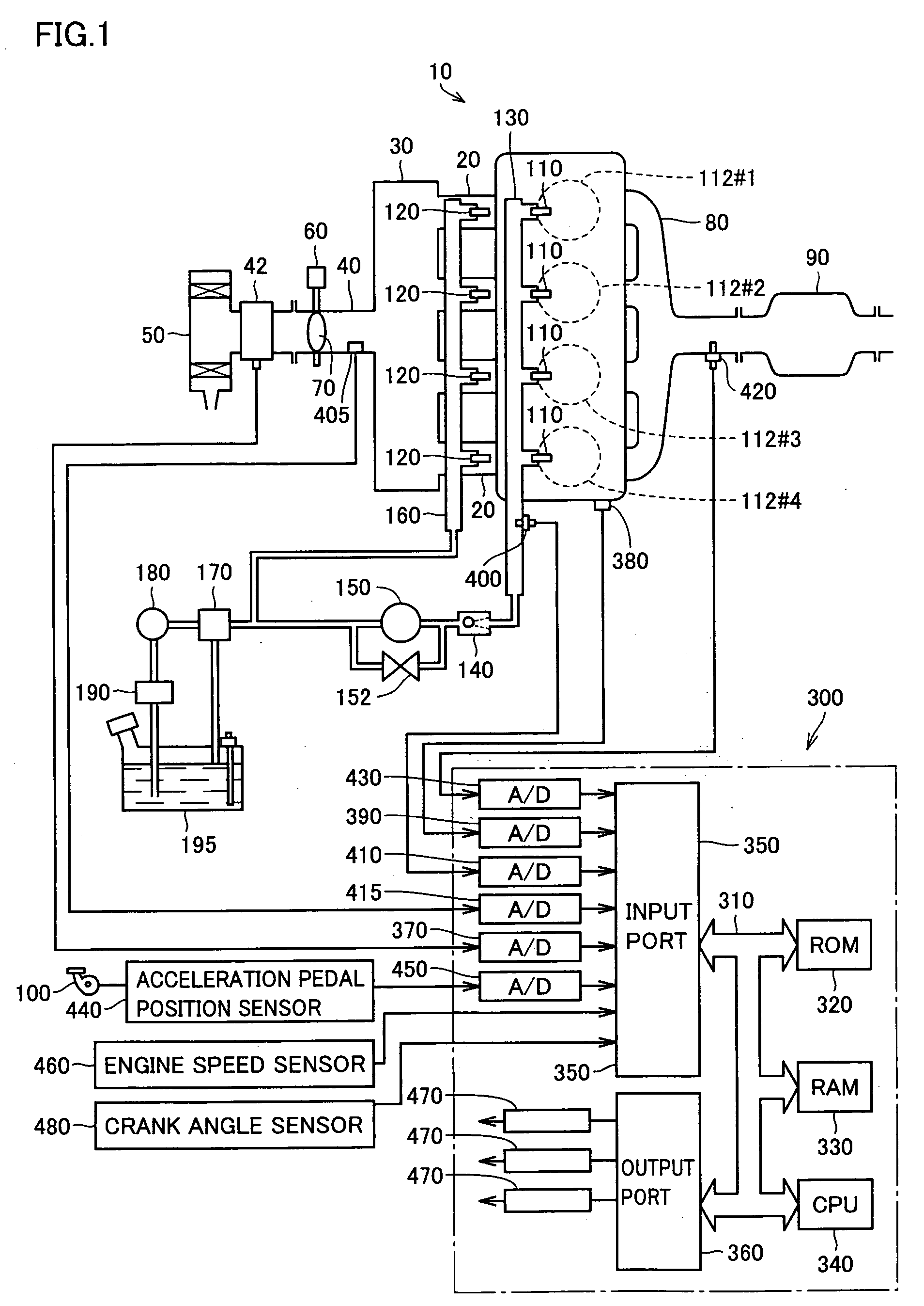
[0036]FIG. 1 is a schematic view of a configuration of an engine system under control of an engine ECU qualified as a control apparatus for an internal combustion engine according to an embodiment of the present invention. Although a straight-4 gasoline engine is shown in FIG. 1, application of the present invention is not limited to such an engine.

[0037] Referring to FIG. 1, an engine (internal combustion engine) 10 includes four cylinders 112#1-112#4. In the following, cylinders 112#1-112#4 will be simply designated “cylinder 112” or “each cylinder 112” when they are to be represented generically without discrimination therebetween.

[0038] A common surge tank 30 is connected to each cylinder 112 via a corresponding inta...


PUM


Abstract

A drive control circuit supplies power to a solenoid coil in an in-cylinder injector of a cylinder in response to a fuel injection signal. A failure detection circuit to detect disconnection failure at an in-cylinder injector is arranged to be shared among cylinders whose phase of each stroke differs 360 degrees in crank angle. An engine ECU detects failure including identification of the injector with disconnection failure based on a failure detection signal from the failure detection circuit, and a crank angle detected by a crank angle sensor. The driver is notified of the failure detection result through the engine ECU.

Description

[0001] This nonprovisional application is based on Japanese Patent Application No. 2005-078459 filed with the Japan Patent Office on Mar. 18, 2005, the entire contents of which are hereby incorporated by reference. BACKGROUND OF THE INVENTION [0002] 1. Field of the Invention [0003] The present invention relates to a control apparatus for an internal combustion engine, particularly a control apparatus including a disconnection failure detection function for a fuel injector. [0004] 2. Description of the Background Art [0005] Fuel injection at an internal combustion engine is generally executed by an injector (fuel injection valve) provided at each cylinder. An injector is formed including a solenoid coil acting as an electromagnet when current is applied in response to a fuel injection signal. The period of fuel injection from the injector must be set precisely in order to achieve an appropriate fuel injection timing and fuel injecting quantity corresponding to the operating state of ...

Claims


Application Information

Patent Timeline
IPC IPC(8): F02D41/22
CPCF02D41/009F02D41/1454F02D41/187F02D41/20F02D41/221F02D41/3094F02D2041/2003F02D2200/0602
Inventor KINOSE, KENICHI
Owner TOYOTA JIDOSHA KK
Why Eureka
Try Eureka