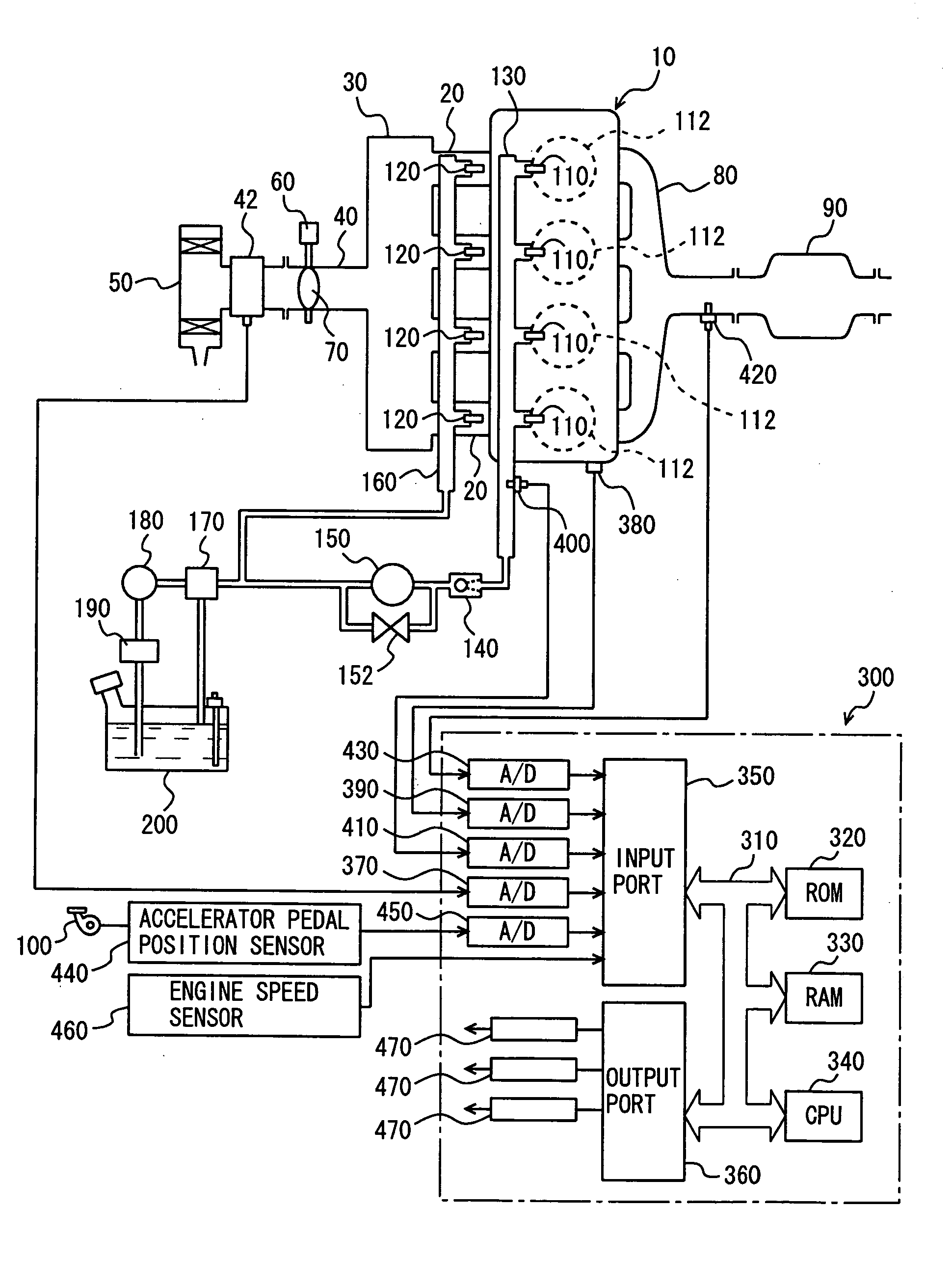
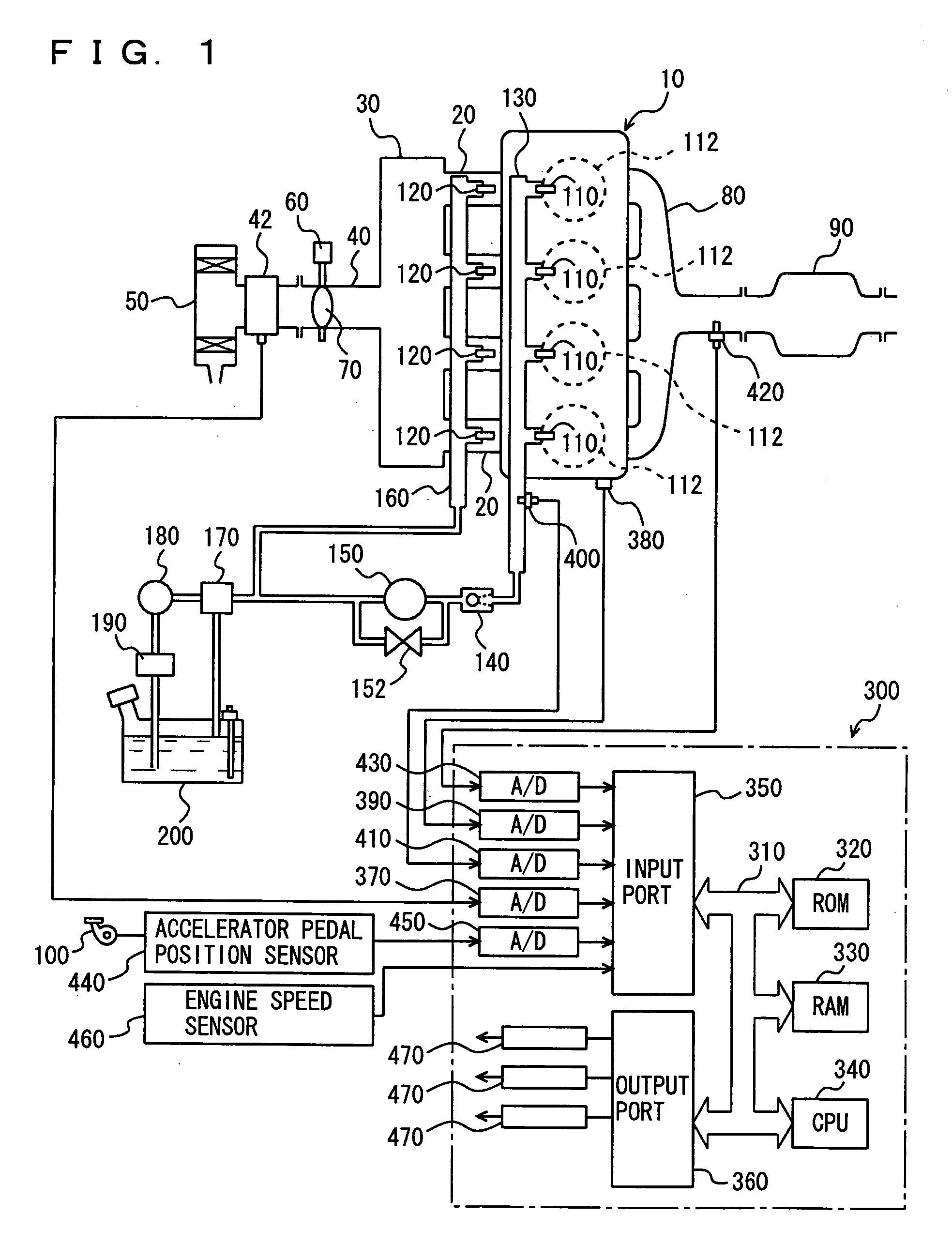
[0013] An object of the present invention is to provide a control apparatus for an
internal combustion engine that includes a first fuel injection mechanism for injecting fuel towards a cylinder and a second fuel injection mechanism for injecting fuel towards the intake manifold or an intake port, allowing air-fuel ratio
feedback control of favorable response.
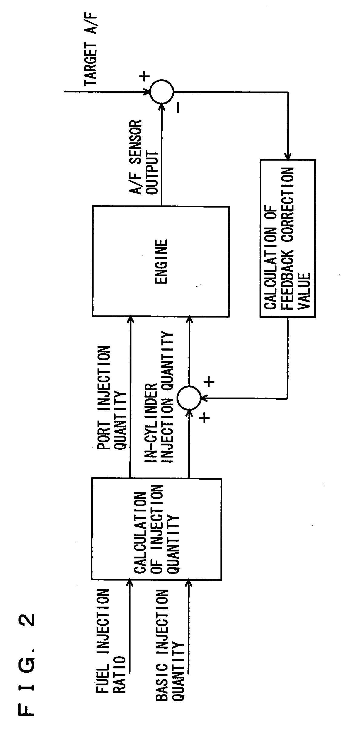
[0015] In the execution of feedback control involving a proportional action corresponding to multiplying the difference between a target air-fuel ratio and sensed air-fuel ratio by a proportional gain, only the quantity of fuel injected by the first fuel injection mechanism that injects fuel into a cylinder (for example, in-cylinder injector) is taken as the control input of the feedback
system in the proportional action. Although the second fuel injection mechanism injecting fuel into an intake manifold (for example, an intake manifold injector) causes
delay time due to the injected fuel adhering to the wall of the intake manifold and the distance up to the
combustion chamber, the in-cylinder injector is absent of such
delay time, allowing a high gain to be set in the proportional action of feedback control. Accordingly, the response in feedback control can be improved. Thus, a control apparatus for an internal
combustion engine including a first fuel injection mechanism injecting fuel towards a cylinder and a second fuel injection mechanism injecting fuel towards the intake manifold or intake port, allowing air-fuel ratio feedback control of favorable response can be provided.
[0017] In addition to the proportional action in the feedback
control system of the present invention, an
integral action to eliminate the
steady state deviation or a derivative action to compensate for the
integral action to improve control stability may be added. Since the fuel injection ratio between the in-cylinder injector and the intake manifold injector is set based on the operation state of the internal
combustion engine in addition to such air-fuel ratio feedback control, the fuel injection ratio will deviate from the injection ratio calculated from the operation state of the internal combustion engine if only the quantity of fuel injected from the intake manifold injector is employed for the control input in the air-fuel ratio feedback control. In view of this issue, the control input of the feedback system in the
integral action is reflected in the fuel injection quantity of the intake manifold injector, whereas the control input of the feedback system in the proportional action and derivative action is reflected in only the fuel injection quantity of the in-cylinder injector. Since the
delay time caused by the fuel injected from the intake manifold injector adhering on the wall does not affect the integral action, a feedback
control system of favorable response and of no
steady state deviation can be realized while obviating significant deviation from the fuel injection ratio of the in-cylinder injector to the intake manifold injector that is calculated based on the operation state of the internal combustion engine. Thus, a control apparatus for an internal combustion engine including a first fuel injection mechanism injecting fuel towards a cylinder and a second fuel injection mechanism injecting fuel towards the intake manifold or intake port, allowing stable air-fuel ratio feedback control of favorable response and of no
steady state deviation can be provided.
[0019] In addition to the proportional action in the feedback control system of the present invention, an integral action to eliminate steady state deviation may be added. Since the fuel injection ratio between the in-cylinder injector and the intake manifold injector is set based on the operation state of the internal combustion engine in addition to such air-fuel ratio feedback control, the fuel injection ratio will deviate from the injection ratio calculated from the operation state of the internal combustion engine if only the quantity of fuel injected from the intake manifold injector is employed for the control input in the air-fuel ratio feedback control. In view of the foregoing, the control input of the feedback system in the integral action is reflected in the fuel injection quantity of the intake manifold injector, whereas the control input of the feedback system in the proportional action is reflected in only the fuel injection quantity of the in-cylinder injector. Since the delay time caused by the fuel injected from the intake manifold injector adhering on the wall does not affect the integral action, a feedback control system of favorable response can be realized while obviating significant deviation from the fuel injection ratio of the in-cylinder injector to the intake manifold injector that is calculated based on the operation state of the internal combustion engine. Thus, a control apparatus for an internal combustion engine including a first fuel injection mechanism injecting fuel towards a cylinder and a second fuel injection mechanism injecting fuel towards the intake manifold or intake port, allowing air-fuel ratio feedback control of favorable response and of no steady state deviation can be provided.
[0023] In accordance with the present invention, there can be provided a control apparatus for an internal combustion engine that includes an in-cylinder injector as the first fuel injection mechanism and an intake manifold injector as the second fuel injection mechanism, partaking in fuel injection, and allowing air-fuel ratio feedback control of favorable response.

