Display device and driving method of the same

a display device and driving method technology, applied in the field of matrix-type display devices, can solve the problems of limited high-speed voltage signals and inability to and achieve the effect of reducing power consumption

Inactive Publication Date: 2006-09-21
NEC ELECTRONICS CORP
View PDF10 Cites 16 Cited by
  • Summary
  • Abstract
  • Description
  • Claims
  • Application Information

AI Technical Summary

Benefits of technology

[0022] An object of the present invention is to provide a display device in which high-speed signal transmission and reduction of power consumption can be realized, and a driving method thereof.
[0024] In the present invention, by generating the complementary current signal based on the image data, the current signal transmits through the wirings for image data. Thus, it is possible to transmit the image data in a high-speed. Further, when the display controller connects neither one of each pair of the wirings for image data to the reference potential terminal and does not set the other one to the floating state based on the image data, that is, when the output of the image data is stopped, the power consumption can be reduced by not allowing the electric current to flow in both of the wirings for image data.
[0026] Thus, by generating the complementary current signal based on the clock signal, the current signal transmits through the wirings for clock signal. Thus, it is possible to transmit the clock signal in a high-speed. In addition, when the output of the clock signal is stopped, it is possible to reduce power consumption by not allowing the electric current to flow in both of the wirings for clock signal.
[0031] In the present invention, by adjusting the frequency of the current signal according to the display mode, it is possible to lower the frequency of the current signal when the image data amount is small. Thus, the power consumption can be reduced.
[0032] Further, the display controller may have a mode register that outputs the control signal according to the display mode of image, and the timing control circuit that sequentially outputs the image data by a frequency adjusted based on the control signal and outputs the receiver control signal showing the display mode of the image. And the source driver may generate the drive signal based on the display mode of the image that the receiver control signal shows. Furthermore, a pair of or plural pairs of the wirings for image data may be provided, the display controller may have an image data switching control circuit that connects either one of each pair of the wirings for image data to the reference potential terminal and sets the other one to the floating state based on the image data, and the source driver may generate a pair of or plural pairs of complementary current signals based on the image data by allowing the electric current to flow in the wiring connected to the reference potential terminal out of the wirings for image data, may generate the drive signal based on the current signals, and may control the magnitude of the electric current allowed to flow in the wirings for image data according to the display mode of the image that the receiver control signal shows. Consequently, since a current value necessary for transmitting the current signal reduces in the display mode such as the subtractive color mode having smaller image data, the current value can be lowered. As a result, it is possible to restrict power consumption.
[0036] According to the present invention, as described above, when the image data is transmitted between the display controller and the source driver in the display device, the high-speed signal transmission and the reduction of power consumption can be realized by transmitting the image data by the current signal and stopping the electric current when the image data is not transmitted.

Problems solved by technology

However, parasitic capacitance of transmission path causes delay if the voltage signal is made to be high-speed, and the level of high-speed voltage signal is limited.
However, the above-described prior art has the following problems.
However, when the image data is transmitted by the current signal, the electric current continuously flows in the wiring between the display controller and the source driver during the dummy transfer, and there exists a problem that the effects to reduce the power consumption is not obtained.

Method used


Image

  • Display device and driving method of the same
  • Display device and driving method of the same
  • Display device and driving method of the same

Examples


first embodiment

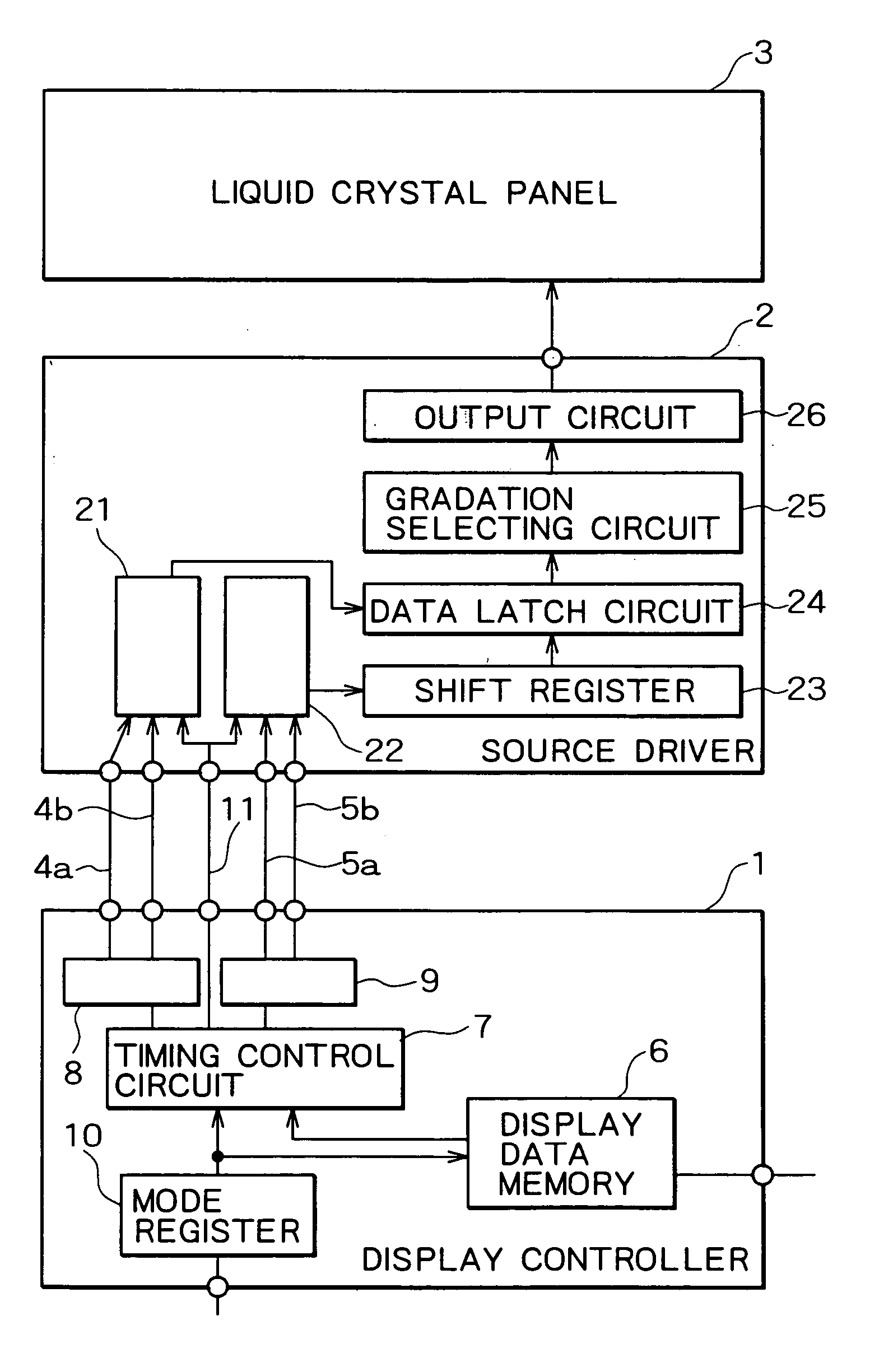
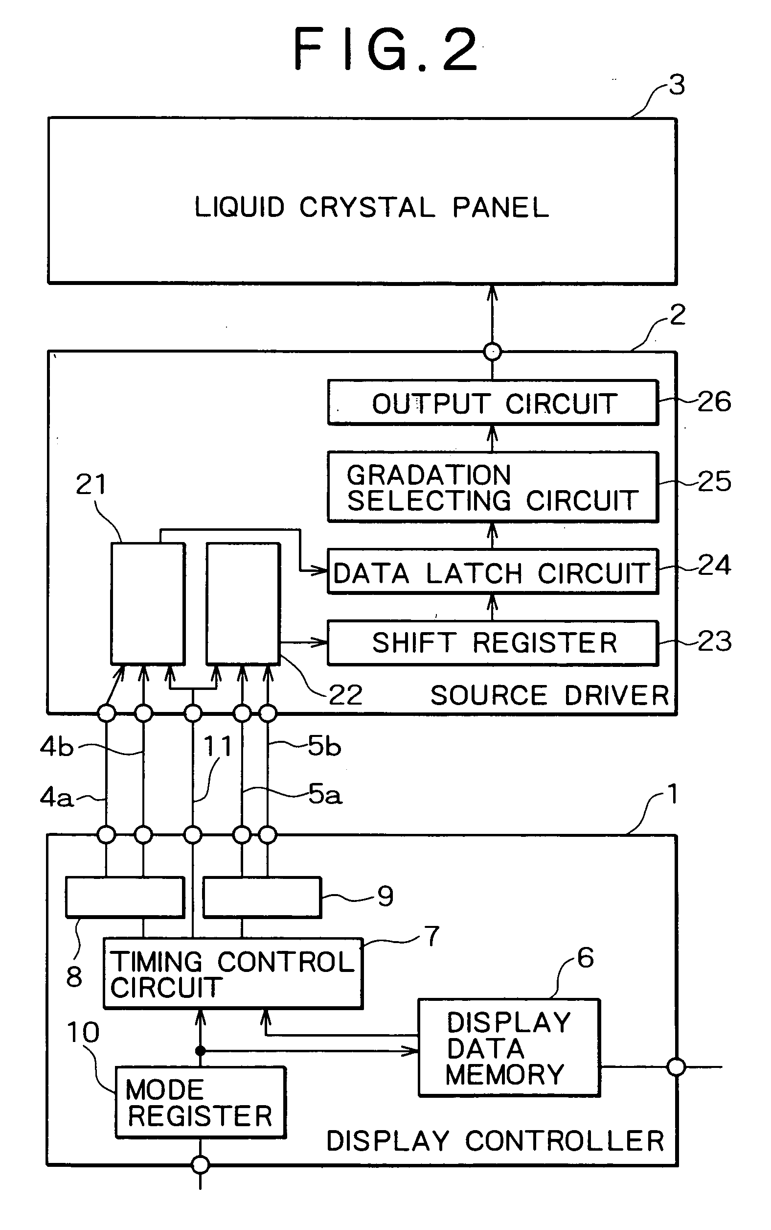
[0052] The preferred embodiments of the present invention will be specifically described with reference to the accompanying drawings. the present invention will be described first. FIG. 2 is the block diagram showing the liquid crystal display device according to the embodiment, FIG. 3 is the circuit diagram showing the V-I conversion circuit for image data of the liquid crystal display device shown in FIG. 2, and FIG. 4 is the circuit diagram showing the I-V conversion circuit for image data of the liquid crystal display device shown in FIG. 2. The liquid crystal display device according to the embodiment is the liquid crystal display device to which the CMADS is applied.

[0053] As shown in FIG. 2, the liquid crystal display device according to the embodiment is provided with a display controller 1, a source driver 2, and a liquid crystal panel 3. Further, two pairs of wirings 4a and 4b, 5a and 5b are provided between the display controller 1 and the source driver 2, and a wiring 11...

third embodiment

[0114] Note that, in the embodiment, the image data amount may be reduced by encoding the image data as shown in the above described

[0115] Next, the fifth embodiment of the present invention will be described. FIG. 14 is the block diagram showing the liquid crystal display device according to the embodiment. As shown in FIG. 14, the embodiment shows an example where a plurality of source drivers 2d are provided in one liquid crystal display device. The applicant developed a technique to sequentially transmit the drive signal between receivers as a technique to efficiently drive a plurality of receivers and disclosed it in Japanese Patent Laid-open No. 2002-026231. The embodiment is the example in which the technique and the present invention are combined. The liquid crystal display device according to the embodiment is provided with one display controller 1, a plurality of source drivers 2d, and one liquid crystal panel 3. Although the wirings 4a, 4b, 5a, 5b, 11 are provided between...

sixth embodiment

[0120] Next, description will be made for the FIG. 15 is the block diagram showing a plasma display panel (PDP) according to the embodiment. The embodiment is an example where the present invention has been applied to the PDP.

[0121] As shown in FIG. 15, the PDP according to the embodiment is provided with a video signal processing circuit 51, a data driver 52 and a panel 53. Further, a pair of wirings 54a, 54b is provided between the video signal processing circuit 51 and the data driver 52. The video signal processing circuit 51 is provided with an inverse gamma processing block 32, an error diffusion or dither block 33, an average picture level computing block 34, an SF coding block 35, a frame memory 36, a drive control block 37, and a V-I conversion circuit 43. Further, the data driver 52 is provided with an I-V conversion circuit 44 and an internal circuit 45. The V-I conversion circuit 43 is connected to one end of the wirings 54a, 54b, and the I-V conversion circuit 44 is co...


PUM

PropertyMeasurementUnit
voltageaaaaaaaaaa
current volumeaaaaaaaaaa
voltage levelsaaaaaaaaaa

Abstract

A display device is provided with a display controller, a source driver, and a liquid crystal panel, and two pairs of wirings are provided between the display controller and the source driver. The display controller is provided with a V-I conversion circuit for image data and a mode register, and the source driver is provided with an I-V conversion circuit for image data. The V-I conversion circuit for image data connects either one of a pair of the wirings to an earth electrode and sets the other one to a floating state based on the image data. The I-V conversion circuit for image data allows electric current to flow in the wiring out of a pair of the wirings, which is connected to the earth electrode, and converts the image data into a pair of complementary current signals to receive them. Further, the I-V conversion circuit for image data stops the current signal by a control signal from the mode register when the image data is not transmitted.

Description

CROSS-REFERENCE TO RELATED PATENT APPLICATIONS [0001] This application is a division of application Ser. No. 10 / 422,774, filed Apr. 25, 2003, now pending, and based on Japanese Patent Application No. 2002-127484, filed Apr. 25, 2003, by Makoto Sunohara, Akimitsu Tajima, Masayuki Yamaguchi, and Masayuki Kumeta. This application claims only subject matter disclosed in the parent application and therefore presents no new matter.BACKGROUND OF THE INVENTION [0002] 1. Field of the Invention [0003] The present invention relates to a matrix type display device that uses electric current as transmitting signal, and a driving method thereof. [0004] 2. Description of the Related Art [0005] The matrix type display device such as a liquid crystal display device and a plasma display panel (also referred to as PDP) is provided with a display controller that sequentially outputs image data, a source driver that generates a drive signal for driving a display panel based on the image data output from...

Claims


Application Information

Patent Timeline
Patent Type & Authority Applications(United States)
IPC IPC(8): G09G3/36G02F1/133G09G3/20G09G5/00H01L51/50H04N5/66
CPCG09G3/28G09G3/36G09G2330/022G09G2320/103G09G2330/021G09G5/006G09G3/20
Inventor SUNOHARA, MAKOTOTAJIMA, AKIMITSUYAMAGUCHI, MASAYUKIKUMETA, MASAYUKI
Owner NEC ELECTRONICS CORP
Why Eureka
Try Eureka