X-ray generation device

a generation device and x-ray technology, applied in the direction of x-ray equipment, electrical equipment, etc., can solve the problems of enlarge the size of the housing and difficulty in accommodating the centrifugal force resistance capacity

Inactive Publication Date: 2006-09-21
HITACHI LTD
View PDF10 Cites 67 Cited by
  • Summary
  • Abstract
  • Description
  • Claims
  • Application Information

AI Technical Summary

Problems solved by technology

However, it has been difficult to accommodate the centrifugal force-resistant capacity in the anode roller bearing portion in the cases of achieving the anode heat capacity or adapting it to a CT device.
However, using the inverter type high-voltage generator with the conventional anode grounded X-ray tube leaves us with no choice but to enlarge the size of its housing in order to withstand the voltage.

Method used


Image

  • X-ray generation device
  • X-ray generation device
  • X-ray generation device

Examples


embodiment 2

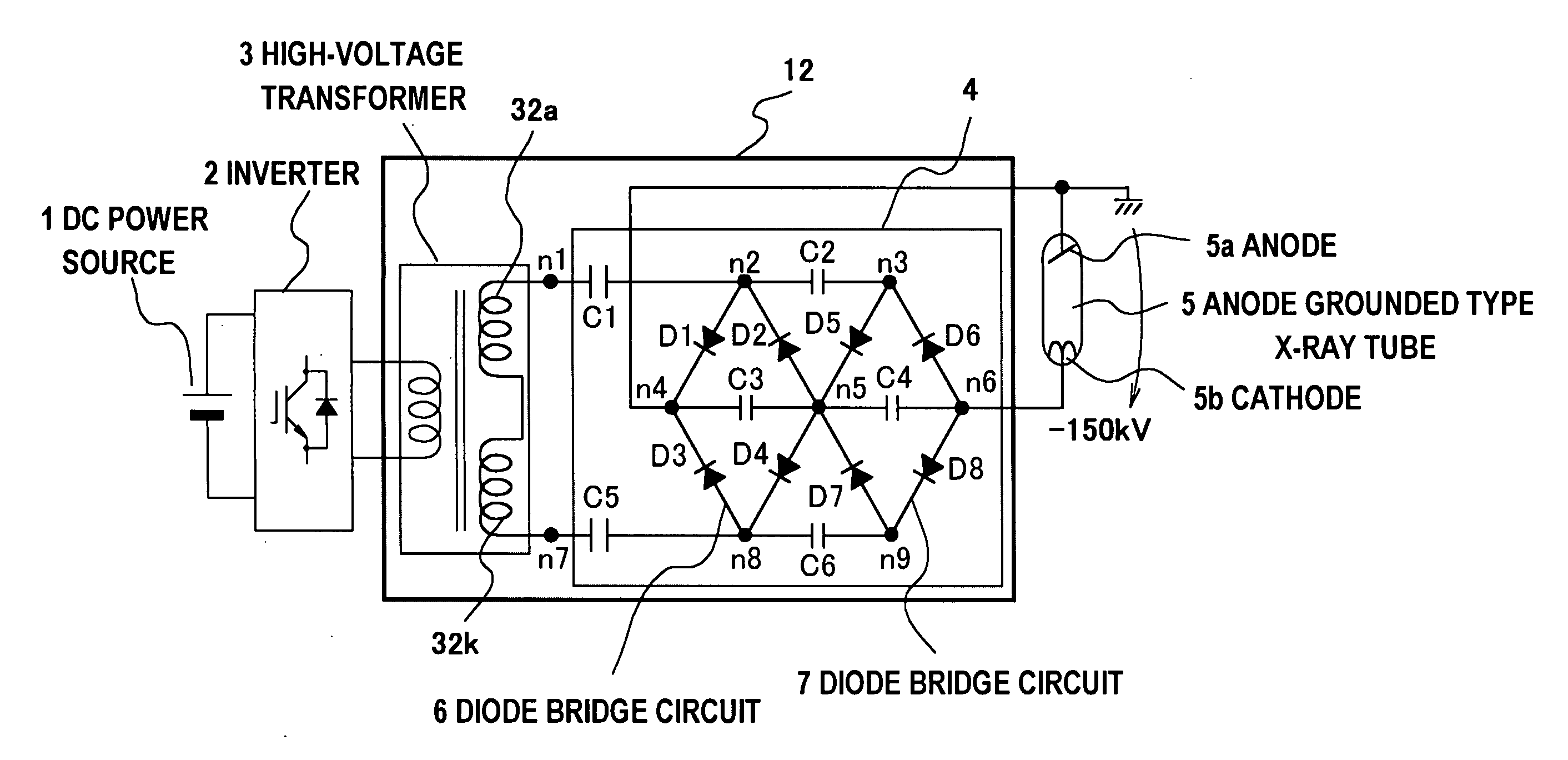
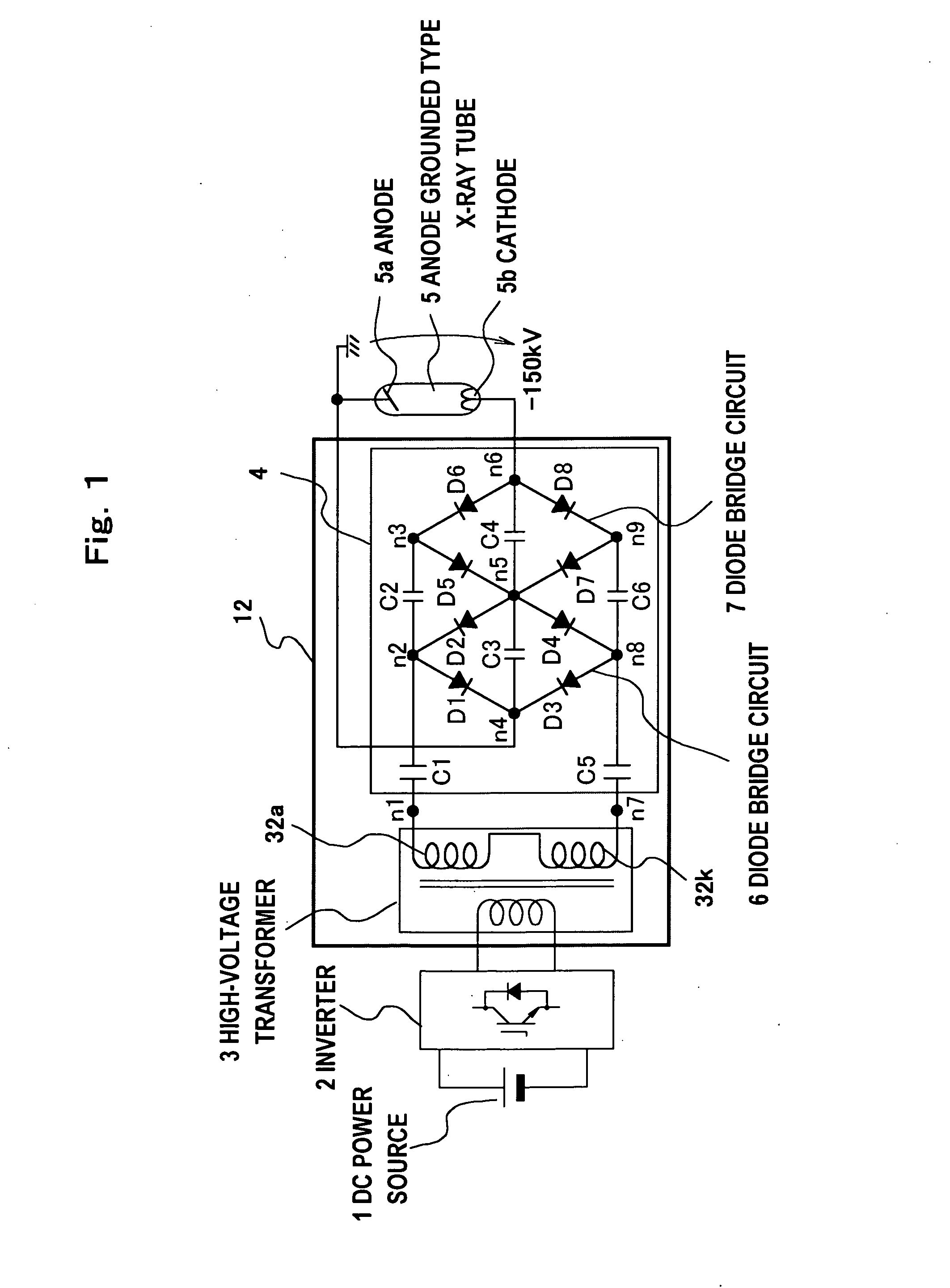
[0057]FIG. 6 is a circuit diagram showing the inverter system X-ray generator according to embodiment 2. For the equivalent with embodiment 1, the detailed explanation will be omitted, with encoding remaining the same. The inverter type X-ray generator according to the mode of the present embodiment, comprises of voltage maintaining means that omits capacitor C5 which was connected between secondary winding 32k and voltage doubling means 4 in high-voltage transformer 4 as shown in FIG. 1 and maintains the voltage peak for a longer period of time than the cycles of inverter 2 by the other capacitors C1, C2, and C6. This is equivalent electric circuit-wise to the mode of the embodiment shown in FIG. 1, thus enabling further reduction in size and cost by reducing the number of capacitors. This kind of configuration is especially helpful in the case of space for installation being limited.

embodiment 3

[0058]FIG. 7 is a circuit diagram showing the inverter type X-ray generator according to embodiment 3. For the equivalent with the embodiment 1, the detailed explanation will be omitted, with encoding remaining the same. In the inverter type X-ray generator according to the present embodiment, secondary windings 32a and 32k of high-voltage transformer 3 and voltage doubling means 4 shown in FIG. 1 are directly connected by omitting capacitor C1 and C5 that were connecting them, capacitor 1 is alternatively connected to the primary side of high-voltage transformer 3, and it configures the voltage maintaining means that maintains the voltage peak for a longer period of time than the cycle of inverter 2. This is equivalent electric circuit-wise to the mode of the embodiment shown in FIG. 1. In this embodiment, it is possible to install the capacitor that maintains the voltage peak on the primary side of the high-voltage transformer, and thus able to improve the latitude for designing t...

embodiment 4

[0059] Even though the X-ray generation device for the anode grounded X-ray tube has been described in embodiment 1 through 3, it is possible to apply the voltage doubling device relating to the present invention to the other technical fields. For example, it can be applied to an electronic microscope that requires high voltage. Despite its small size and weight, it can generate voltage manifold of its source, with stability and reduced voltage variation.


PUM


Abstract

Between terminals of secondary windings in a high-voltage transformer (3), there are connected in parallel input side terminals of a plurality of diode full bridge circuits each via voltage maintaining means such as a capacitor maintaining a voltage peak value for a longer period than the cycle of an inverter (2). Between the input side terminals of the diode full bridge circuits, there are connected voltage maintaining means such as capacitors maintaining a voltage peak value for a longer period than the cycle of the inverter. Moreover, the output side terminals of the diode full bridges are connected in series via smoothing means such as almost equivalent smoothing capacitors and between the output side terminals, an anode grounding type X-ray tube (5) is connected. Thus, it is possible to realize a small-size and light-weight device at a reduced cost and reduce the ripple in the output voltage while using the anode grounding type X-ray tube.

Description

TECHNICAL FIELD [0001] The present invention relates to a high-voltage device wherein a high-voltage transformer is able to output severalfold of voltage. It particularly relates to an inverter type X-ray generator that converts a direct current (DC) power source into alternating current (AC) of high frequency by an inverter. It boosts the outputted voltage through a high-voltage transformer, generates DC high voltage by rectifying it, and applies it to an anode grounded X-ray tube. BACKGROUND OF THE INVENTION [0002] An X-ray generator is generally known as a device to generate X-rays to irradiate the diagnostic region of the body of a subject, and is comprised of an X-ray tube which irradiates X-rays and a high-voltage generator which generates high-voltage DC (hereinafter referred to as the tube voltage) to apply to said X-ray tube. The neutral grounded type has mainly been used for the stated X-ray generator. However, it has been difficult to accommodate the centrifugal force-res...

Claims


Application Information

Patent Timeline
Patent Type & Authority Applications(United States)
IPC IPC(8): H05G1/12H05G1/20
CPCH05G1/12
Inventor TAKAHASHI, JUNTAKANO, HIROSHI
Owner HITACHI LTD
Why Eureka
Try Eureka