
Inkjet recording element comprising particles and polymers

a technology of particles and polymers, applied in the direction of duplicating/marking methods, coatings, printing, etc., can solve the problems of poor image stability in these systems, easy smudges, and slow swelling, and achieve the effect of high stability to ambient ozon

Inactive Publication Date: 2006-09-21
EASTMAN KODAK CO
View PDF2 Cites 12 Cited by
  • Summary
  • Abstract
  • Description
  • Claims
  • Application Information

AI Technical Summary

Benefits of technology

[0024] The colloidal particles and associated polymers can be coated and dried to form an inkjet recording element that has the required glossiness, is touch-dry after inkjet printing and provides an environment in which the dyes show high stability to ambient ozone. BRIEF DESCRIPTION OF TIE DRAWINGS
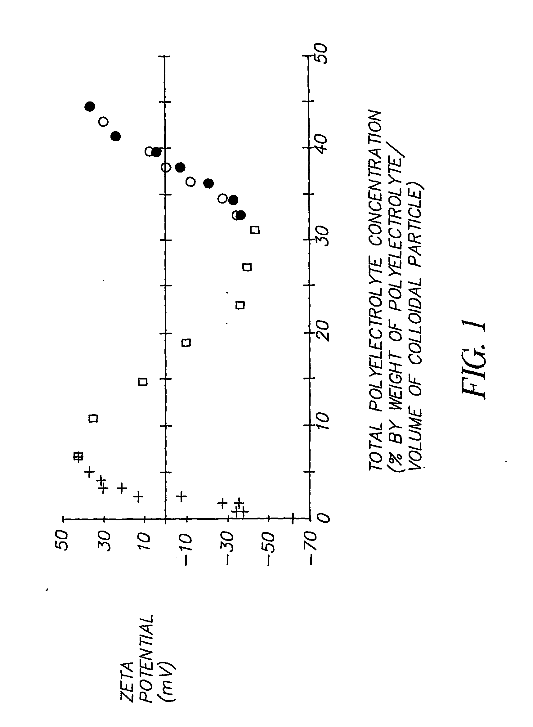
[0025]FIG. 1 is a plot of total polyelectrolyte concentration against zeta potential, showing the zeta charge potential of anionic silica particles on sequential addition of polyelectrolytes, wherein
[0026] (a) + indicates the addition of varying amounts of 2 kD polyethyleneimine to silica;
[0027] (b) □ indicates the addition of 200 kD sodium polystyrene sulfonate to a silica / 2 kD polyethyleneimine composite; and
[0028] (c) ● and (d) ◯ indicate composites containing exactly equal amounts of silica, 2 kD polyethyleneimine and 200 kD sodium polystyrene sulfonate, with varying amounts of 750 kD polyethyleneimine. However in
[0029] (c) ● three polymers were added to silica in three sequential steps whilst in

Problems solved by technology

However, the image stability in these systems is poor when exposed to environmental ozone.
Swelling slows the absorption and so prints smudge easily after printing.
The dip method is not straightforwardly adapted to colloidal particles.
The extra steps that are necessary between every addition of polymer would preclude their use in economically viable paper coating processes.
There is no disclosure of any commercially-viable method for making inkjet receiver layers of practical thickness.

Method used


Image

  • Inkjet recording element comprising particles and polymers
  • Inkjet recording element comprising particles and polymers

Examples


example 1

Schematic Representation of the Formation of PEMs on Colloidal Particles

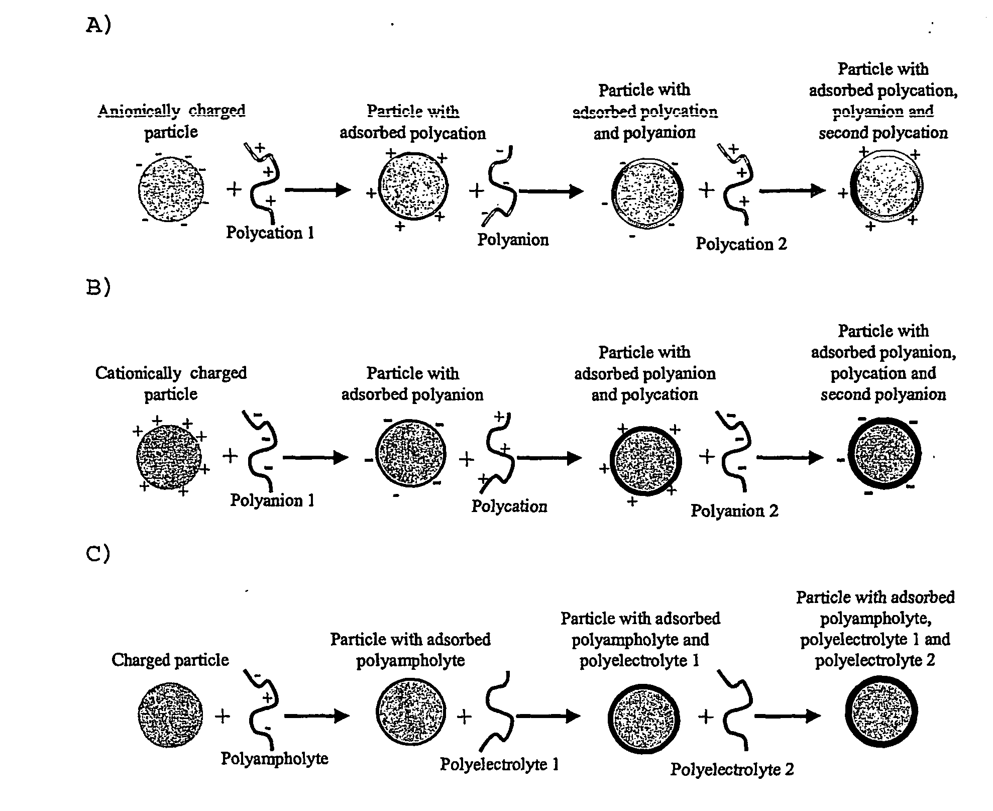
[0071] The following are schematic representations of some ways in which it is envisaged that the sequential association to a colloidal particle of polyelectrolytes may occur, leading to sequential charge reversals and build-up of a multilayer. The diagrams are included to assist in understanding the invention, without being bound by theory of the actual mechanisms that may be involved. It will also be understood that in addition to sequential association, for example as represented herein, the polyelectrolytes may alternatively be added as a mixture and not sequentially.

[0072] In these diagrams, the polyelectrolytes contain ionised or ionisable groups. Although the polyelectrolytes are drawn as highly charged, it may be possible that under the pH conditions of mixing the polymers are essentially uncharged. The addition of a third polyelectrolyte may cause charge reversal of the particle / polymer composite (as...

example 2

Coating of Particles

(a) Method

[0073] The coating formulations were made according to the experimental procedures described below. The formulations described all contained 15% w / w silica, corresponding to a volume fraction of 7.43%. Hand coatings were made from these formulations, with a blade set with a gap of 150 μm onto a 100 μm thick polyethylene terephthalate film with a 50 mg.m−2 dry gelatin ‘subbing’ layer. The film was held on a stainless steel platen by vacuum. Unless indicated the platen was maintained at 30 C by circulating water. The coatings were dried on the platen at this temperature, taking up to 45 min. to dry.

[0074] Where indicated, stirring was carried out using a magnetic stirrer bar. Filtration was carried out by transferring the sample into a syringe and passing through a 26 mm diameter cellulose acetate filter (Sartorius MINIART™) with pores of 5 μm diameter.

[0075] Each example relied on mixing colloidal suspensions and polymer solutions. The volume ratio...

example 3

Analysis of FIG. 1

[0081] In the experiments on which FIG. 1 is based the anionic silica used was LUDOX™ PW50 of particle diameter 77 nm. All materials are fully described in the Table above. In FIG. 1 and the following discussion the amount of polymer present is expressed as percentage weight of polymer per volume of particle. This is a useful measure as it is independent of the final particle concentration.

[0082] The zeta potential of a particle is a measure of the effective surface charge of the particle at the hydrodynamic slipping plane. The zeta potential may be determined from a particle's electrophoretic mobility. Here, the zeta potential was measured with a Malvern Zetasizer 3000HS instrument. For these measurements, the parent suspensions were diluted to 0.0500 v / v % (in the absence of polyelectrolyte) or 0.01250 v / v % (in the presence of polyelectrolyte) silica to avoid multiple scattering. All zeta potential measurements were made with solutions at 0.01 M NaCl at 25° C....


PUM

PropertyMeasurementUnit
equivalent spherical diameteraaaaaaaaaa
diameteraaaaaaaaaa
diameteraaaaaaaaaa

Abstract

The invention provides an inkjet recording element comprising a support having thereon an image-receiving layer, said inkjet recording element containing colloidal particles having a charged or chargeable surface and having associated therewith at least two polymers having ionised or ionisable groups thereon, wherein one of those polymers has ionised or ionisable groups of opposite charge to that of the surface of the colloidal particles and another of those polymers has ionised or ionisable groups the same as that of the surface of the colloidal particles. When printed with ink the element can impart good image stability, has a short dry time, can give any required gloss, provides good optical density and is suitable for use with a wide range of inks.

Description

FIELD OF THE INVENTION [0001] The invention relates to an inkjet recording element comprising colloidal particles having ionised or ionisable surface groups and polyelectrolyte species of different charge types. BACKGROUND OF THE INVENTION [0002] In a typical inkjet et recording or printing system, ink droplets are ejected from a nozzle at high speed towards a recording element to produce an image on the element. The ink droplets, or recording liquid, generally comprise a recording agent, such as a dye or pigment, and a large amount of solvent. The solvent, or carrier liquid, typically is made up of water and an organic material such as a monohydric alcohol, a polyhydric alcohol or mixtures thereof [0003] An inkjet recording element typically comprises a support having on at least one surface thereof an ink-receiving or image-receiving layer, and includes those intended for reflection viewing, which have an opaque support, and those intended for viewing by transmitted light, which h...

Claims


Application Information

Patent Timeline
Patent Type & Authority Applications(United States)
IPC IPC(8): B41M5/00B41M5/52
CPCB41M5/52B41M5/5218B41M5/5236B41M5/5245
Inventor HOWE, ANDREW M.WESLEY, ROBIN D.
Owner EASTMAN KODAK CO
Learn More