System and method of nox abatement

a technology of nox abatement and exhaust system, which is applied in the direction of machine/engine, mechanical equipment, separation processes, etc., can solve the problems of increasing the difficulty of reducing the number of nox-containing exhaust by the exhaust after treatment system, increasing the fuel ratio, and increasing the difficulty of reducing the number of nox-containing exhaus

Inactive Publication Date: 2006-09-28
DELPHI TECH INC
View PDF13 Cites 127 Cited by
  • Summary
  • Abstract
  • Description
  • Claims
  • Application Information

AI Technical Summary

Benefits of technology

[0008] An embodiment of a NOX abatement system comprises: a first NOX adsorber capable of being disposed in-line and downstream of and in fluid communication with an engine; a selective catalytic reduction catalyst disposed in-line and downstream of and in direct fluid communication with the first NOX adsorber, wherein the selective catalytic reduction catalyst is capable of storing ammonia; and an off-line reformer disposed in selective communication with and upstream of the first NOX adsorber and the selective catalytic reduction catalyst, wherein the reformer is capable of producing a reformate comprising primarily hydrogen and carbon monoxide.

Problems solved by technology

Reduction of the flame temperatures can lead to significant increases in hydrocarbons, carbon monoxide, soot, and engine power.
The reduction of NOX into nitrogen (N2) by an exhaust after treatment system is increasingly difficult as the air fuel ratio increases.
However, three-way conversion catalysts are generally inefficient in the reduction of NOX.
However, this period of fuel-rich combustion may also result in a significant fuel penalty.
These components, in addition to the urea supplying components, however, add bulk and size to the device and thereby restrict its usage to heavy-duty applications.
Further, the added complexity of the urea injection and the lack of a urea distribution infrastructure are significant detractors to using urea injection.
The use of such elevated temperatures generally causes an undesirable amount of additional fuel to be consumed in the operation of the selective catalyst reduction system.

Method used


Image

  • System and method of nox abatement
  • System and method of nox abatement
  • System and method of nox abatement

Examples


Embodiment Construction

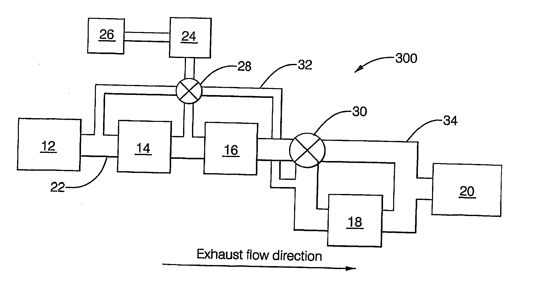
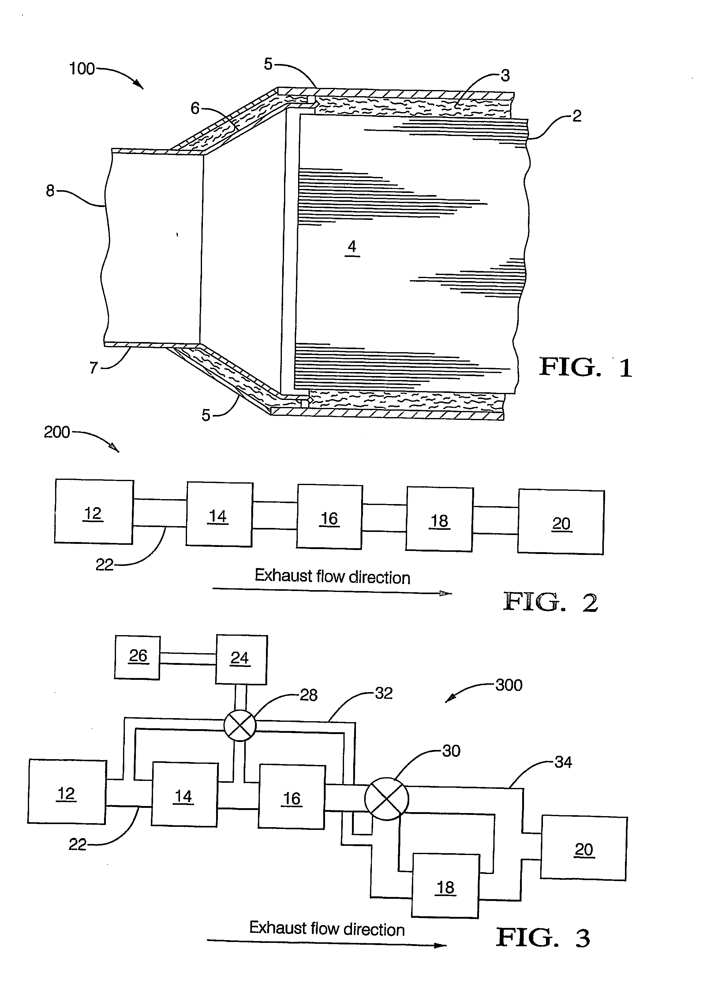
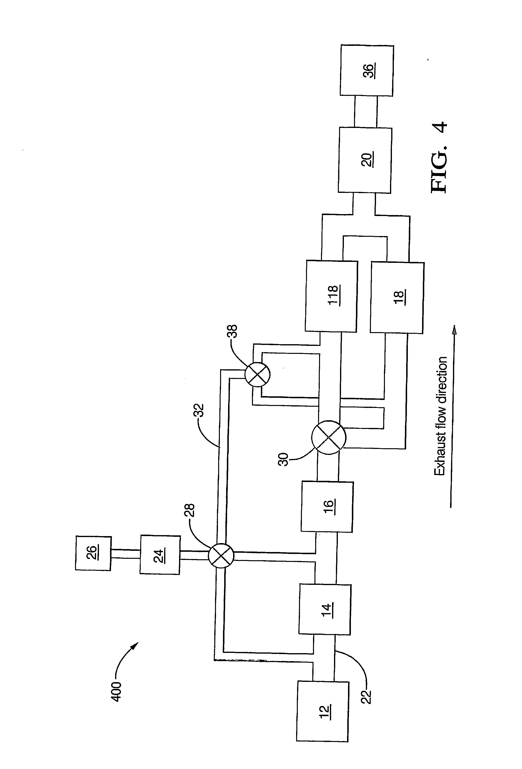
[0026] Disclosed herein is an on-board system for the production of ammonia using on-board generated NOX as well as an on-board generated reformate comprising primarily hydrogen and carbon monoxide, i.e., greater than or equal to 80% of the total volume of reformate is hydrogen and carbon monoxide. Preferably, greater than or equal to 90% of the reformate are hydrogen and carbon monoxide. The term “on-board” is used herein to refer to the production of a given component within a vehicle (e.g., automobile, truck, etc.) system. While all embodiments disclosed herein use “on-board” production of ammonia and / or reformate, as will be discussed in greater detail, these components may be produced “in-line” or “off-line”. The term “line” refers to an exhaust fluid stream. As such, “in-line” refers to production of a component, e.g., ammonia, within the exhaust fluid stream, whereas “off-line” production refers to the production of a given component outside of an exhaust fluid stream. The co...


PUM

PropertyMeasurementUnit
Si/Al molar ratioaaaaaaaaaa
vol %aaaaaaaaaa
vol %aaaaaaaaaa

Abstract

A NOx abatement system comprising: a first NOx adsorber (18) capable of being disposed in-line and downstream of and in fluid communication with an engine (12); a selective catalytic reduction catalyst (20) disposed in-line and downstream of and in direct fluid communication with the first NOx adsorber (18), wherein the selective catalytic reduction catalyst (20) is capable of storing ammonia; and an off-line reformer (24) disposed in selective communication with and upstream of the first NOx adsorber (18) and the selective catalytic reduction catalyst (20), wherein the reformer (24) is capable of producing a reformate comprising primarily hydrogen and carbon monoxide.

Description

BACKGROUND [0001] This disclosure relates generally to a method and system for reducing nitrogen oxides (NOX) and for regenerating particulate filters. [0002] Generally, diesel engines release more undesirable NOX per kilometer into the atmosphere than gasoline engines. This is because diesel engines generally operate at higher flame temperatures in order that the diesel fuel might burn. Reduction of the flame temperatures can lead to significant increases in hydrocarbons, carbon monoxide, soot, and engine power. For at least these reasons, the flame temperatures are generally not reduced, thereby producing the NOX. The reduction of NOX into nitrogen (N2) by an exhaust after treatment system is increasingly difficult as the air fuel ratio increases. The reduction of NOX, e.g., nitric oxide (NO), nitrogen dioxide (NO2), and nitrous oxide (N2O), in exhaust fluid is a widely addressed problem as a result of environmental concerns and mandated government emissions regulations, particula...

Claims


Application Information

Patent Timeline
Patent Type & Authority Applications(United States)
IPC IPC(8): F01N3/00B01D53/94F01N3/023F01N3/035F01N3/08F01N3/20F01N13/02F01N13/04
CPCB01D53/9431B01D2255/206F01N3/0231F01N3/035F01N3/0814F01N3/0821F01N3/0828F01N3/0842F01N3/0878F01N3/206F01N3/2066F01N2240/02F01N2240/25F01N2240/28F01N2240/30F01N2410/04F01N2570/18F01N2610/02F01N2610/04Y02T10/24F01N13/0093F01N13/009F01N13/011Y02A50/20Y02T10/12
Inventor KUPE, JOACHIMZIZELMAN, JAMESBOTTI, JEAN J.SIMPKINS, HASKELLHEMINGWAY, MARK D.LABARGE, WILLIAM J.SILVIS, THOMAS W.KIRWAN, JOHNEBONADIES, JOSEPH V.PRICE, KENNETH
Owner DELPHI TECH INC
Why Eureka
Try Eureka