Internal combustion engine cooling system
a cooling system and internal combustion engine technology, applied in the direction of machines/engines, mechanical equipment, instruments, etc., can solve the problems of abnormal temperature of the coolant flowing into abnormal cooling of the internal combustion engine, and abnormal cooling of the coolant through the radiator. achieve the effect of preventing an internal combustion engine from overheating, reducing fuel consumption, and reducing fuel consumption
- Summary
- Abstract
- Description
- Claims
- Application Information
AI Technical Summary
Benefits of technology
Problems solved by technology
Method used
Image
Examples
first embodiment
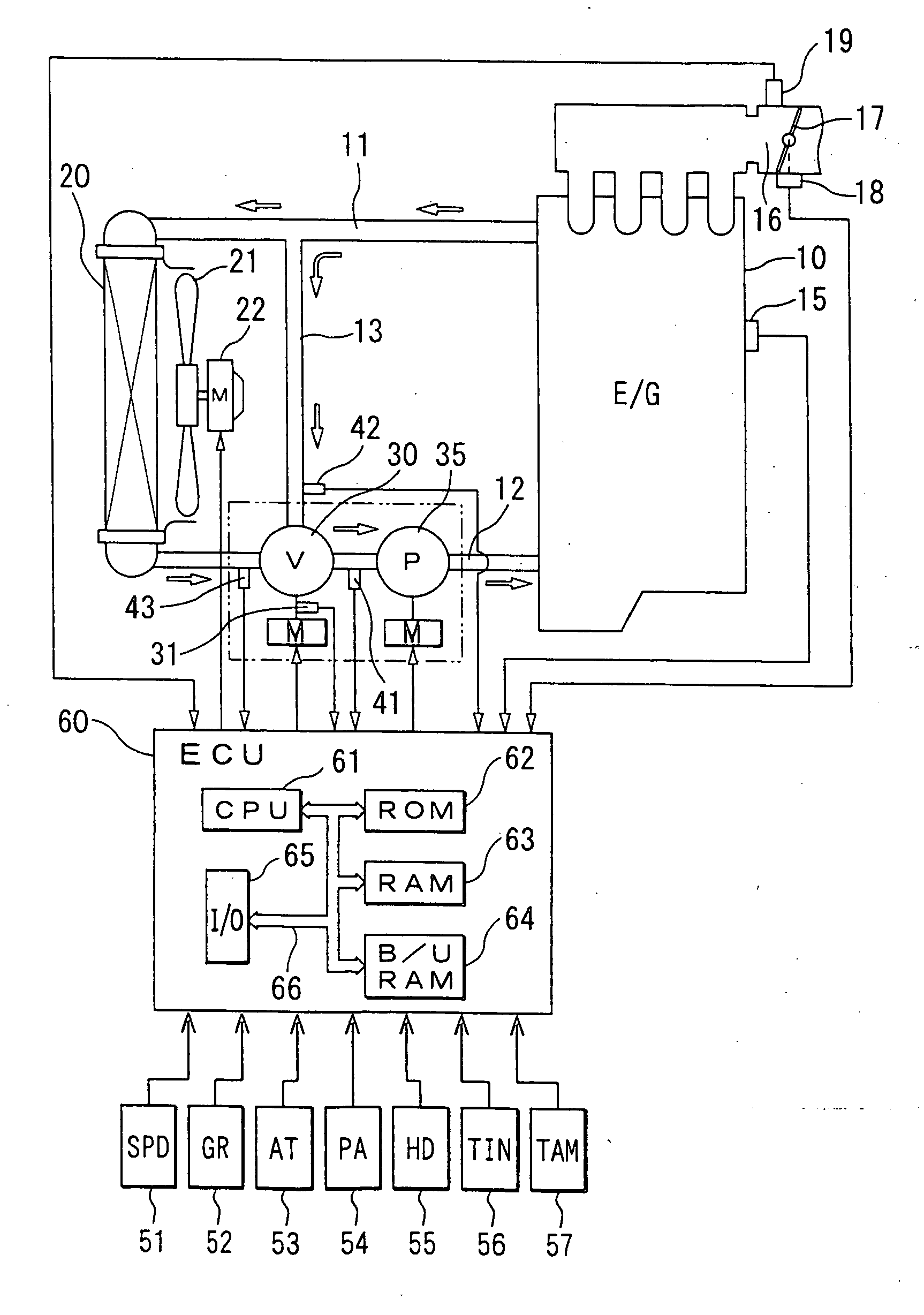
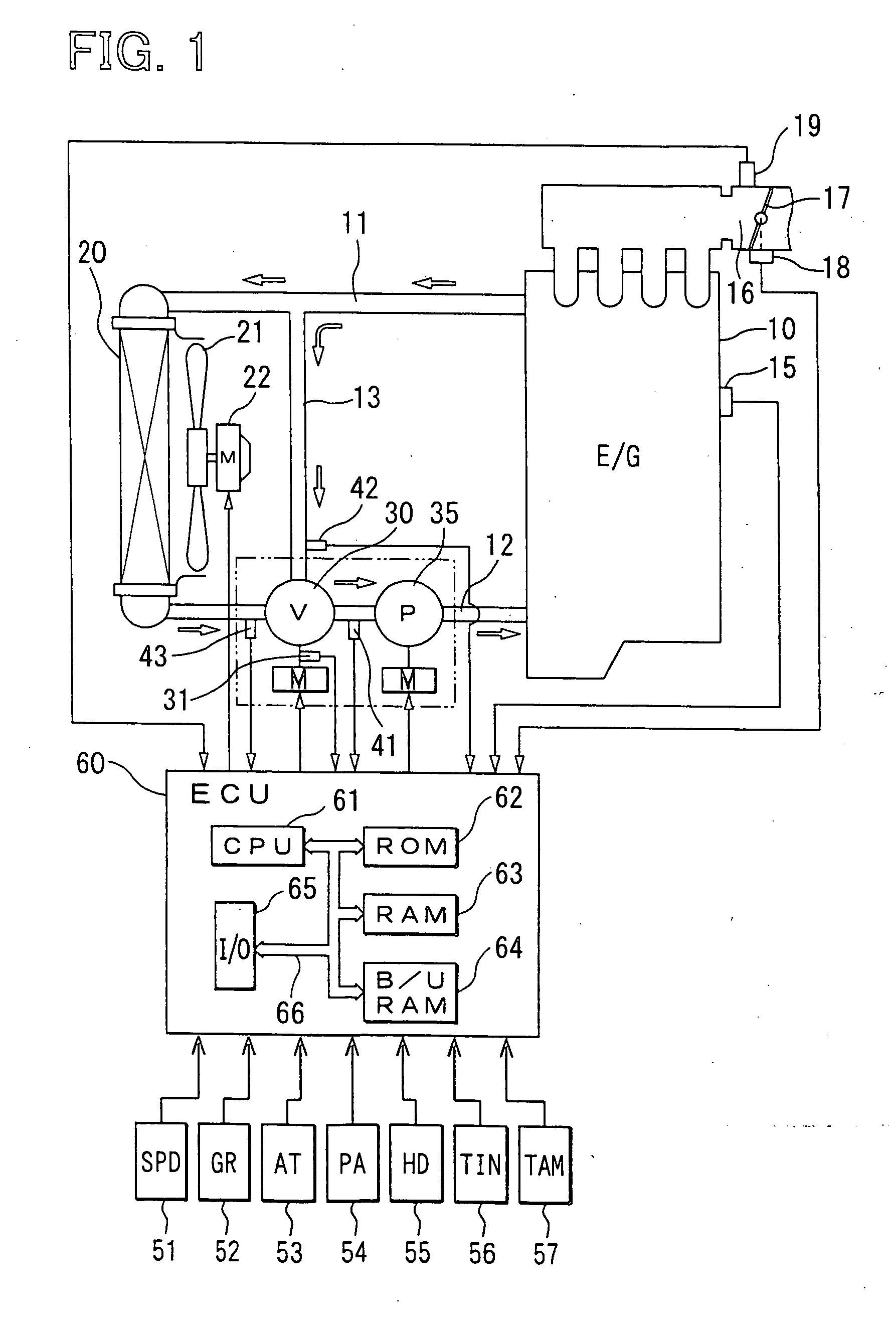
[0036] Referring to FIG. 1, an internal combustion engine 10 is connected to a radiator 20 for cooling engine cooling water (coolant) following through an inlet passage 11 and an outlet passage 12. The inlet passage 11 and the outlet passage 12 are connected by a bypass passage 13. A rotary flow control valve 30 is placed at the junction of the outlet passage 12 and the bypass passage 13. An electric water pump 35 is placed between the flow control valve 30 and the engine 10 in the outlet passage 12. A radiator fan 21 is disposed behind the radiator 20. A fan motor 22 drives the radiator fan 21 when necessary.
[0037] A potentiometer 31 is combined with the valve shaft, not shown, of the flow control valve 30 to measure the valve opening of the flow control valve 30. A first coolant temperature sensor 41 for measuring the temperature of the coolant flowing into the electric water pump 35, i.e., inlet coolant temperature is placed between the flow control valve 30 and the electric mot...
second embodiment
[0047] A traveling mode determining routine shown in FIG. 3 and a coolant temperature control routine shown in FIG. 4 carried out in the second embodiment will be described. The CPU 61 repeats the traveling mode determining routine and the coolant temperature control routine at a predetermined period.
[0048] Referring to FIG. 3, the ECU 60 receives the engine speed signal NE, i.e., a signal indicating the operating condition of the engine 10, provided by the engine speed sensor 15, the intake pressure signal PM, i.e., a signal indicating load on the engine 10, provided by the intake pressure sensor 19, and the vehicle speed signal SPD provided by the vehicle speed sensor 51 or the AT control signal AT provided by an AT controller 53 at step 201. At step 202, a traveling mode, i.e., an uphill traveling mode, a downhill traveling mode or a level traveling mode, is determined from maps stored in the ROM 62 by using the engine speed signal, the intake pressure signal and the gear ratio ...
third embodiment
[0055] A steady / transient traveling state determining routine shown in FIG. 5 and a coolant temperature control routine shown in FIG. 6 carried out by the ECU 60 in the third embodiment will be described. The CPU 61 repeats the steady / transient traveling state determining routine and the coolant temperature control routine at a predetermined period.
[0056] Referring to FIG. 5, the ECU 60 receives the engine speed signal NE, i.e., a signal indicating the operating condition of the engine 10, provided by the engine speed sensor 15, the intake pressure signal PM, i.e., a signal indicating load on the engine 10, provided by the intake pressure sensor 19, and the vehicle speed signal SPD provided by the vehicle speed sensor 51 or the AT control signal AT provided by the AT controller 53 at step 301. Then, at step 302, an integrated change of loads (intake pressure, throttle opening and amount of intake air) on the engine 10 or an integrated change of engine speed is calculated for steady...
PUM
 Abstract
Description
Claims
Application Information
 - R&D Engineer
- R&D Manager
- IP Professional
- Industry Leading Data Capabilities
- Powerful AI technology
- Patent DNA Extraction
Browse by: Latest US Patents, China's latest patents, Technical Efficacy Thesaurus, Application Domain, Technology Topic, Popular Technical Reports.
© 2024 PatSnap. All rights reserved.Legal|Privacy policy|Modern Slavery Act Transparency Statement|Sitemap|About US| Contact US: help@patsnap.com


