Hybrid interconnect for a solid-oxide fuel cell stack

a fuel cell and hybrid technology, applied in the field of fuel cells, can solve the problems of relatively rapid oxidation of ferrritic stainless steel, and achieve the effects of reducing thermal expansion differences, reducing thermal stress, and reducing the ability of the joint to withstand multiple thermal cycles

Inactive Publication Date: 2006-09-28
DELPHI TECH INC
View PDF6 Cites 16 Cited by
  • Summary
  • Abstract
  • Description
  • Claims
  • Application Information

AI Technical Summary

Benefits of technology

[0009] Briefly described, a fuel cell electrical interconnect in accordance with the invention comprises a peripheral frame, formed of one or more materials having a CTE similar to that of adjacent elements to which the interconnect must be bonded, and a central portion formed of a corrosion-resistant material for conducting electric current between adjacent fuel cells. The central portion is attached to the peripheral frame via a wide gap brazed, brazed joint, or welded joint, for relieving thermal expansion differences between the frame and the central portion. Preferably, the joint includes a braze layer which may or may not include a ductile interlayer, for example, a nickel, copper, gold or silver layer, which helps to relieve thermal stress between the frame and the central portion of the interconnect and aids in the ability of the joint to withstand multiple thermal cycles. A conductive path is formed between the anode and associated central portion of the interconnect by a metal mesh that freely passes oxygen, such as a silver mesh, and between the cathode and associated central portion formed of materials such as a nickel based superalloy, such as Haynes 230, or a silver mesh.

Problems solved by technology

In general, the desirable corrosion-resistant alloys are not good CTE matches for sealing into a fuel cell stack, which has resulted in the use of ferritic stainless steels.
However, ferritic stainless steels oxidize relatively rapidly at temperatures above 650° C.

Method used


Image

  • Hybrid interconnect for a solid-oxide fuel cell stack
  • Hybrid interconnect for a solid-oxide fuel cell stack
  • Hybrid interconnect for a solid-oxide fuel cell stack

Examples


Embodiment Construction

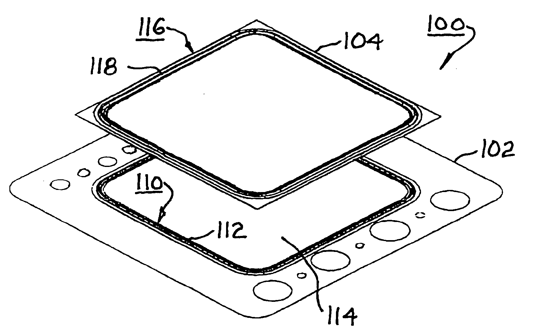
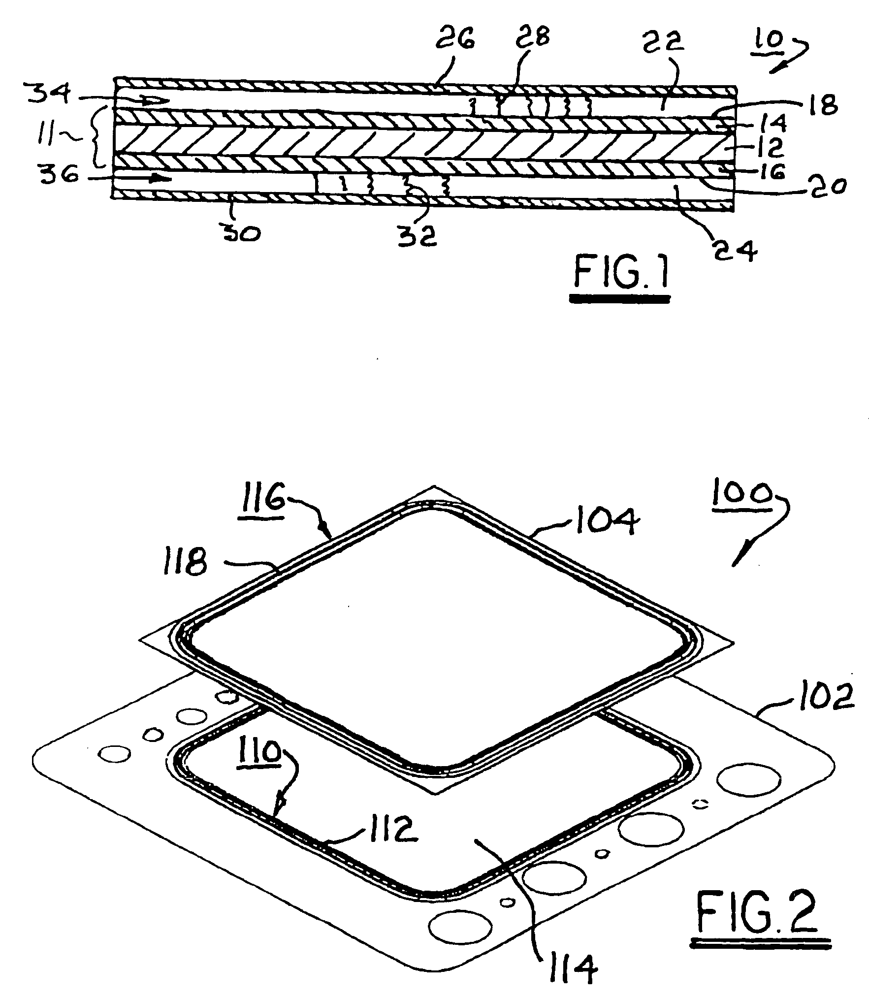
[0015] Referring to FIG. 1, a portion of a fuel cell subassembly 10 includes structural and electrochemical elements known in the art of solid-oxide fuel cells. The example shown is of a class of such fuel cells said to be “anode-supported” in that the anode is a structural element having the electrolyte and cathode deposited upon it. Thus, element thicknesses as shown in FIGS. 1 and 2 are not to scale. A complete fuel cell stack assembly includes fuel cell subassemblies electrically connected, in series.

[0016] In the portion of fuel cell subassembly 10 shown in FIG. 1, each fuel cell subassembly includes an electrode 11 having an electrolyte element 12 separating an anodic element (anode) 14 and a cathodic element (cathode) 16. The electrolyte element preferably is formed of a ceramic oxide and preferably includes zirconia stabilized with yttrium oxide (yttria), known in the art as YSZ. The cathode is formed of, for example, porous lanthanum strontium manganate or lanthanum stront...


PUM

PropertyMeasurementUnit
temperaturesaaaaaaaaaa
coefficient of thermal expansionaaaaaaaaaa
resistant to corrosionaaaaaaaaaa

Abstract

An electrical interconnect for a fuel cell assembly comprising a peripheral frame formed of one or more materials having a coefficient of thermal expansion similar to that of adjacent elements to which the interconnect must be bonded and a central portion formed of a corrosion-resistant material for conducting electric current between adjacent fuel cells. Preferably, the central portion is attached to the peripheral frame via a brazed corrugated lap joint for relieving thermal expansion differences between the frame and the central portion. Preferably, the joint includes an interlayer of a ductile material, for example, a nickel, copper, silver or gold layer, which helps to relieve thermal stress between the frame and the central portion.

Description

[0001] This invention was made with United States Government support under Government Contract / Purchase Order No. DE-FC26-02NT41022. The Government has certain rights in this invention.TECHNICAL FIELD [0002] The present invention relates to fuel cells; more particularly, to solid-oxide fuel cells; and most particularly, to an improved electrical interconnect for a fuel cell, the interconnect comprising a frame formed of a first alloy having a coefficient of thermal expansion (CTE) matching the CTE of adjacent fuel cell elements to which the frame is bonded, and an electrically-conductive insert formed of a second alloy resistant to fuel- or air-induced corrosion. BACKGROUND OF THE INVENTION [0003] Fuel cells for combining hydrogen and oxygen to produce electricity are well known. A known class of fuel cells includes a solid-oxide electrolyte layer through which oxygen anions migrate; such fuel cells are referred to in the art as “solid-oxide” fuel cells (SOFCs). [0004] In some appli...

Claims


Application Information

Patent Timeline
Patent Type & Authority Applications(United States)
IPC IPC(8): H01M8/02H01M8/24B32B3/10
CPCH01M8/0208H01M8/021H01M8/0223H01M8/0247Y10T428/24273H01M2008/1293Y02E60/50Y02E60/525H01M8/2465H01M8/0297H01M8/2425
Inventor ENGLAND, DIANE M.WILSON, LANEMUKERJEE, SUBHASISHVAVONESE, CATHERINE
Owner DELPHI TECH INC
Why Eureka
Try Eureka