

Contact pad and bump pad arrangement for high-lead or lead-free bumps
a contact pad and bump pad technology, applied in the direction of basic electric elements, electrical apparatus construction details, solid-state devices, etc., can solve the problems of toxic materials, high-speed off-chip interconnection, toxic material, etc., to reduce stress, improve reliability of the resulting assembly, and the effect of extra effor
- Summary
- Abstract
- Description
- Claims
- Application Information
AI Technical Summary
Benefits of technology
Problems solved by technology
Method used
Image

Examples
Embodiment Construction
[0017] The making and using of the presently preferred embodiments are discussed in detail below. It should be appreciated, however, that the present invention provides many applicable inventive concepts that can be embodied in a wide variety of specific contexts. The specific embodiments discussed are merely illustrative of specific ways to make and use the invention, and do not limit the scope of the invention.
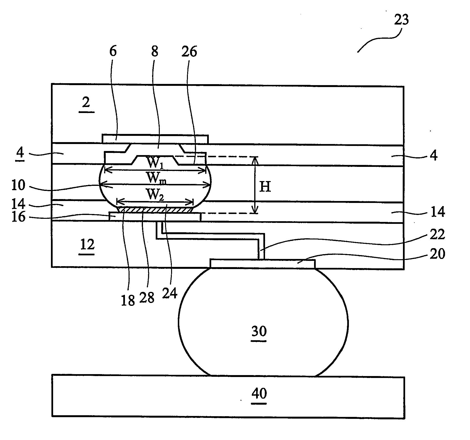
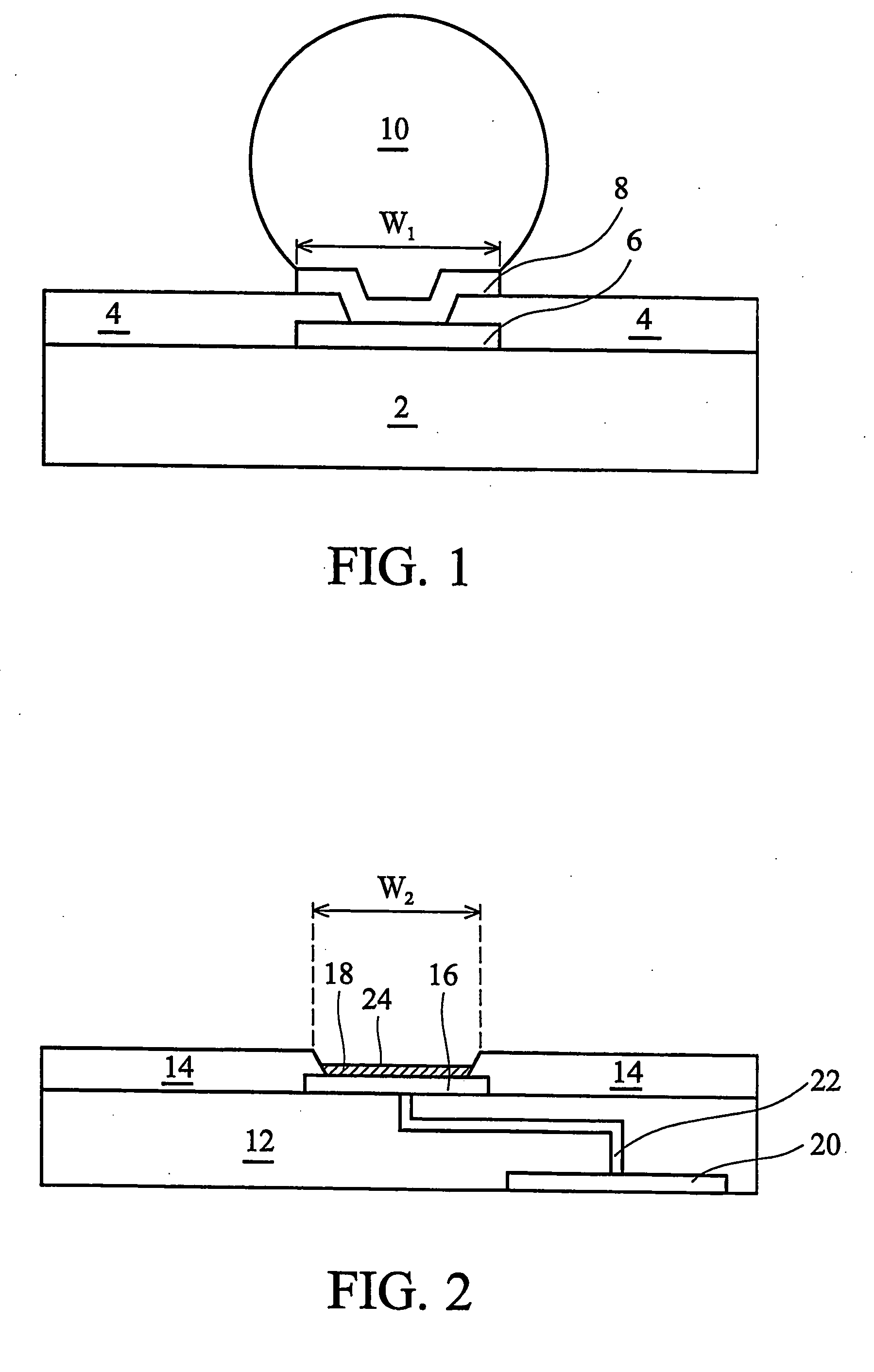
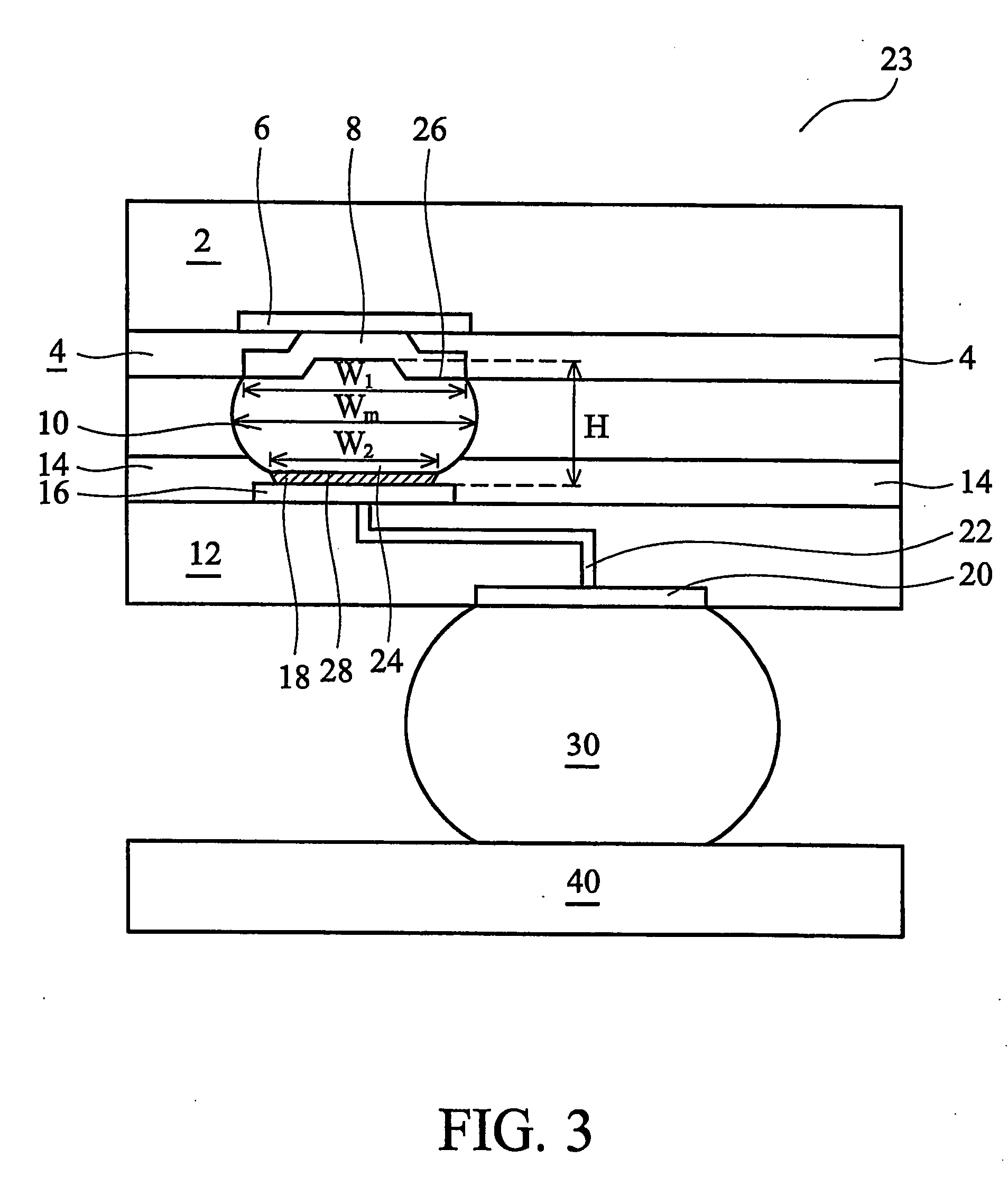
[0018] The preferred embodiment of the present invention presents a package assembly structure that uses lead-free or high-lead-containing bumps. The preferred embodiments are illustrated in FIGS. 1 through 4 wherein like reference numbers are used to designate like elements throughout the various views and illustrative embodiments of the present invention.
[0019] In the preferred embodiment, solder bumps are formed on chips, which contain integrated circuits. In other embodiments, the solder bumps are formed on package substrates. FIG. 1 illustrates a semiconductor substra...
PUM
 Abstract
Description
Claims
Application Information