
Magnetic sensor

a magnetic sensor and sensor technology, applied in the field of magnetic sensors and magnetic recording and reproducing apparatus, can solve the problems of lowering the mr ratio, high noise component, and disadvantageous failure of tmr elements to achieve high signal-to-noise ratio (snr)

Active Publication Date: 2006-10-05
KK TOSHIBA
View PDF4 Cites 55 Cited by
  • Summary
  • Abstract
  • Description
  • Claims
  • Application Information

AI Technical Summary

Benefits of technology

[0009] A magnetic sensor according to an aspect of the present invention comprises: a magnetic oscillation element including a first magnetic resonance layer, a second magnetic resonance layer, a nonmagnetic layer sandwiched between the first and second magnetic resonance layers, and a pair of electrodes which supply a current perpendicularly to planes of the first resonan...

Problems solved by technology

However, the TMR element provides not only a high level of real signal component but also a high level of noise component resulting from shot noise.
Thus, the TMR element disadvantageously fails to achieve a high signal-to-noise ratio (SNR).
A thinner tunnel insulating layer is likely to short the circuit between the upper and lower ferromagnetic layers, thus lowering the MR ratio.
This makes it markedly difficult to produce a reliable element.
In recent years, magnetic white noise has been a problem for all these MR elements.
However, no technique for applying such a spin-wave oscillator to a magnetic sensor or the like is known.

Method used


Image

  • Magnetic sensor
  • Magnetic sensor
  • Magnetic sensor

Examples


example 1

[0046] In the present example, a magnetic oscillation element is produced and oscillation characteristics thereof are measured. The example will be described below. FIG. 8A is a plan view of a coplanar guide including the magnetic oscillation element produced in the present example. FIG. 8B is a sectional view of FIG. 8A. FIG. 8C is a detailed sectional view of a magnetic oscillation element in FIG. 8B. The coplanar guide is produced by depositing a metal thin film on a sapphire substrate (not shown) by sputtering and processing the metal thin film by electron beam lithography.

[0047] As shown in FIGS. 8A and 8B, two ground plates 101, 101 spaced at a distance of 100 μm are connected at their ends by a Ru layer 102 with a width of 5 ρm and a thickness of 100 nm. The magnetic oscillation element 10, an Au layer 103 with a thickness of 100 nm, and a waveguide 104 are formed on the Ru layer 102. As shown in FIG. 8C, the magnetic oscillation element is formed of a stack of the Ru layer ...

example 2

[0051] In the present example, measurement of a signal voltage will be described. An integrating circuit with a time constant of about 10 ns is connected to the magnetic oscillation element in place of the amplifier and spectrum analyzer in FIG. 9. A synchroscope is used to measure the output voltage (signal voltage) of the magnetic oscillation element with the pulse field shown in FIG. 11A applied to the element. FIG. 11B shows measurements of the signal voltage. As shown in FIG. 11B, a signal with an amplitude of 0.5 mV is obtained.

example 3

[0052] In the present example, measurement of a signal voltage obtained with a system in which a band-pass filter is added will be described. A Gaussian band-pass filter is interposed between the bias tee and the integrating circuit in the measurement system used in Example 2. The band-pass filter has a maximum transmittance of 98%, a center frequency of 11.9 GHz, and a full-width at half maximum of 0.5 GHz. As in the case of Example 2, a synchroscope is used to measure the output voltage (signal voltage) of the magnetic oscillation element with the pulse field shown in FIG. 12A applied to the element. FIG. 12B shows measurement of the signal voltage. As shown in FIG. 12B, the amplitude increases to about 1 mV.

[0053]FIG. 13 shows a perspective view of a magnetic recording and reproducing apparatus 150 according to an embodiment of the present invention. A magnetic disk (magnetic recording medium) 151 is mounted on a spindle 152 and rotated in the direction of arrow A by a spindle m...


PUM


Abstract

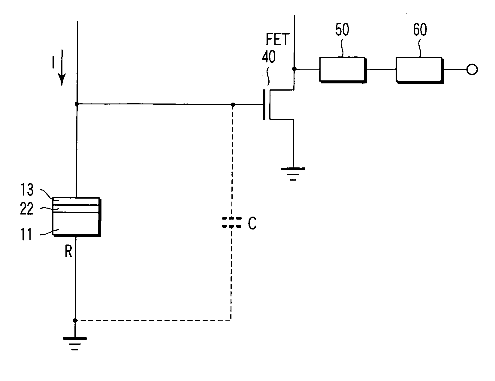
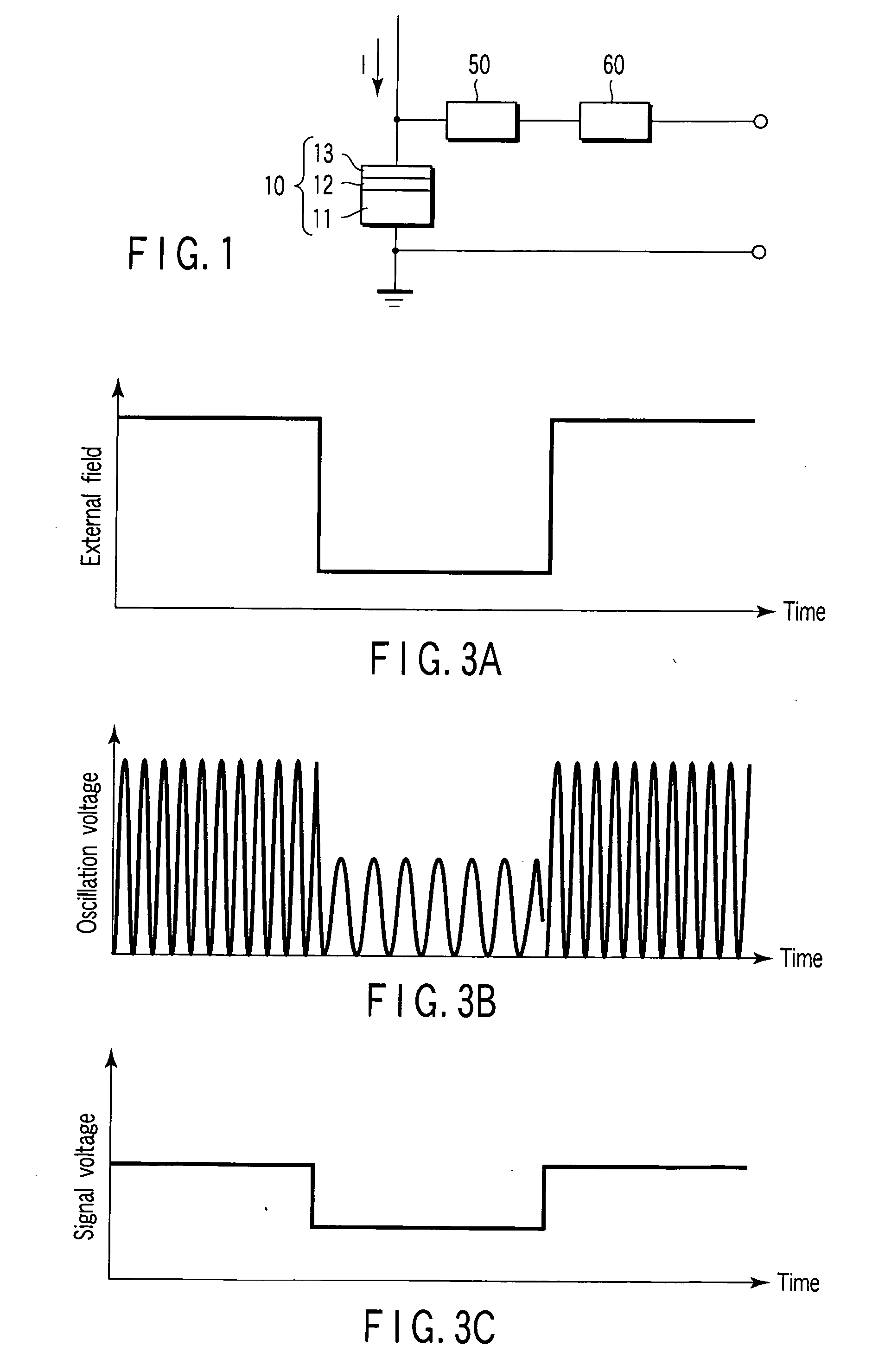
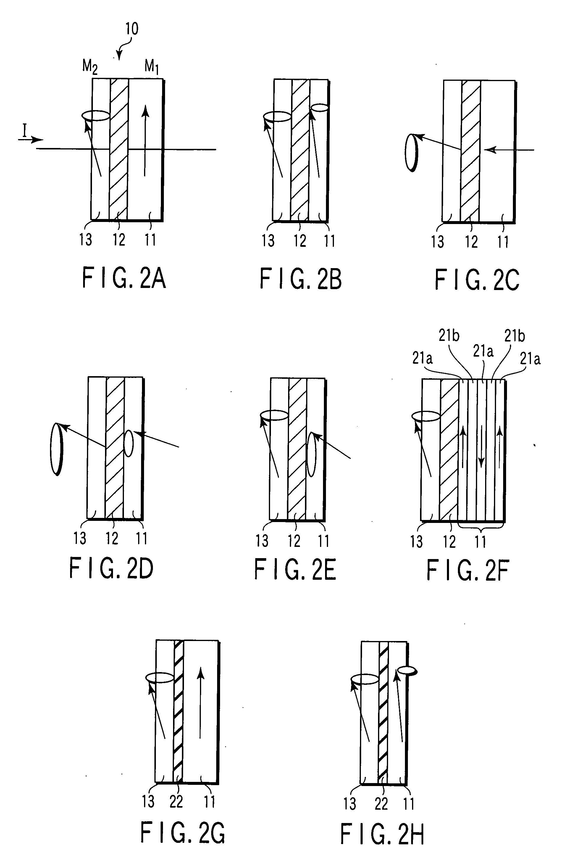
A magnetic sensor has a magnetic oscillation element including a first magnetic resonance layer, a second magnetic resonance layer, a nonmagnetic layer sandwiched between the first and second magnetic resonance layers, and a pair of electrodes which supply a current perpendicularly to planes of the first resonance layer, the nonmagnetic layer and the second magnetic resonance layer, and a monitor monitoring a change dependent on an external magnetic field in a change of a high-frequency oscillation voltage generated across the magnetic oscillation element due to precession of magnetization in at least one of the first and second magnetic resonance layers caused by supplying the current.

Description

CROSS-REFERENCE TO RELATED APPLICATIONS [0001] This application is based upon and claims the benefit of priority from prior Japanese Patent Application No. 2005-104470, filed Mar. 31, 2005, the entire contents of which are incorporated herein by reference. BACKGROUND OF THE INVENTION [0002] 1. Field of the Invention [0003] The present invention relates to a magnetic sensor and a magnetic recording and reproducing apparatus having a magnetic head including the magnetic sensor. [0004] 2. Description of the Related Art [0005] Magnetic recording density has increased significantly since the advent of a giant magnetoresistive head (GMR head) that utilizes a giant magnetoresistive effect (GMR effect). A GMR element includes a stacked film (what is called a spin valve film) having a sandwich structure comprising a ferromagnetic layer, a nonmagnetic layer, and a ferromagnetic layer. The GMR element applies an exchange bias to one of the ferromagnetic layers to fix magnetization thereof, whi...

Claims


Application Information

Patent Timeline
IPC IPC(8): G11B5/33
CPCB82Y10/00B82Y25/00G11B2005/3996G11B5/3929G11B2005/0016G01R33/093
Inventor SATO, RIEKUDO, KIWAMU
Owner KK TOSHIBA
Learn More