Lens holder and laser array unit using the same

a laser array unit and lens holder technology, applied in the field of lens holder and laser array unit using the same, can solve the problems of high positional difficulty, inability to secure the high bonding strength between the lens holder and the heat block, and the surface of the holder with the heat block inevitably becoming long, so as to achieve high face alignment accuracy, and high bonding strength. the effect of strain

Inactive Publication Date: 2006-10-05
ADTEC ENG +1
View PDF4 Cites 60 Cited by
  • Summary
  • Abstract
  • Description
  • Claims
  • Application Information

AI Technical Summary

Benefits of technology

[0038] The lens holder according to the present invention is formed such that the length of the surface for bonding the lens array or elongated lens in the direction orthogonal to the optical axis direction of the lens is longer than the length of the surface to be bonded to a certain other fixing member, such as the heat block or the like in the same direction, unlike the conventional lens holders formed in rectangular solid. Thus, the former length may be set long enough to improve the face alignment accuracy with the lens array or elongated lens. On the other hand, the latter length may be set appropriately short within a range which secures the bonding strength to minimize the strain that may occur at the bonded section due to the temperature change, thereby unsticking or the like arising from the strain may be prevented.
[0040] In the lens holder according to the present invention, it is necessary to take into account the entire bonding surface when considering the magnitude of the strain in the bonded section. As described above, from the viewpoint of minimizing the strain in the bonded section, the maximum length of the bonding surface is preferably short. On the other hand, a wider bonding surface provides a stronger bonding strength which is desirable for realizing stable fixation. Thus, it is desirable that the surface to be bonded is shaped substantially in square having the same horizontal and vertical size in order to secure the maximum bonding strength while minimizing the strain. More preferably, it is shaped substantially in regular polygon having the same length in every direction, including diagonal direction, or substantially in round.
[0042] In the mean time, the laser array unit according to the present invention uses the lens holder according to the present invention described above. Thus, a high face alignment accuracy between the lens array or elongated lens and the lens holder for fixedly bonding it may be obtained, and the strain in the bonded section between the lens holder and a certain other fixing member (laser supporting member or the reference member where the laser supporting member is fixed) may be minimized.
[0043] Further, when the laser array units according to the present invention further includes a single optical fiber and the condensing optical system as described above to form a beam combining laser unit, a high face alignment accuracy between the lens array or elongated lens and optical fiber may be obtained since a high face alignment accuracy is ensured between the lens array or elongated lens and lens holder. Consequently, the laser beams may be coupled to the optical fiber with a high coupling efficiency.
[0044] Still further, when the laser array is constituted by GaN semiconductor lasers, the amount of heat generated by the laser array is greater compared with the case where it is constituted by other types of semiconductor lasers. Thus, the temperature change in the laser supporting member having the laser array fixed thereon also is greater when the laser array is activated or deactivated. Accordingly, the strain arising from the temperature change is more likely to occur at the bonded section between the laser supporting member and the lens holder, and between the reference member having the laser supporting member fixed thereon and the lens holder. Consequently, application of the present invention to a laser array unit constituted by GaN semiconductor lasers may provide a more significant strain preventing effect.

Problems solved by technology

In such case, it has been a problem that it is difficult to secure both high bonding strength between the lens holder and heat block, and high positional accuracy for fixing the collimating lens array to the lens holder.
That is, the problem often found in a beam combining laser module in which each of a plurality of laser beams emitted from the semiconductor laser array is collimated by each of the collimating lenses of the collimating lens array, condensed by a single condenser lens, and coupled to the optical fiber will be detailed hereinbelow.
Conventional lens holders are shaped in a rectangular solid, so that if they are made larger in order to improve the face alignment accuracy with the collimating lens, then the bonding surface of the holder with the heat block inevitably becomes lengthy, which leads to unsticking of the bonded section.
On the other hand, if they are made smaller in order to avoid the unsticking of the bonded section, the face alignment accuracy is degraded.
The above description is a problem that may occur in the case where a lens array is fixedly bonded to a lens holder, and then the holder is fixedly bonded to a heat block.
But a similar problem may occur in the case where an elongated lens, such as a cylindrical lens or the like is fixedly bonded to a lens holder instead of the lens array, or where the lens holder is fixedly bonded to a fixing member other than the heat block.
Further, even if the fixing member such as the heat block and the lens holder have the identical thermal expansion coefficient, if the adhesive layer between them has a high heat insulating property, which is normally the case, the same problem of strain development may also occur when subjected to the temperature change.

Method used


Image

  • Lens holder and laser array unit using the same
  • Lens holder and laser array unit using the same
  • Lens holder and laser array unit using the same

Examples


first embodiment

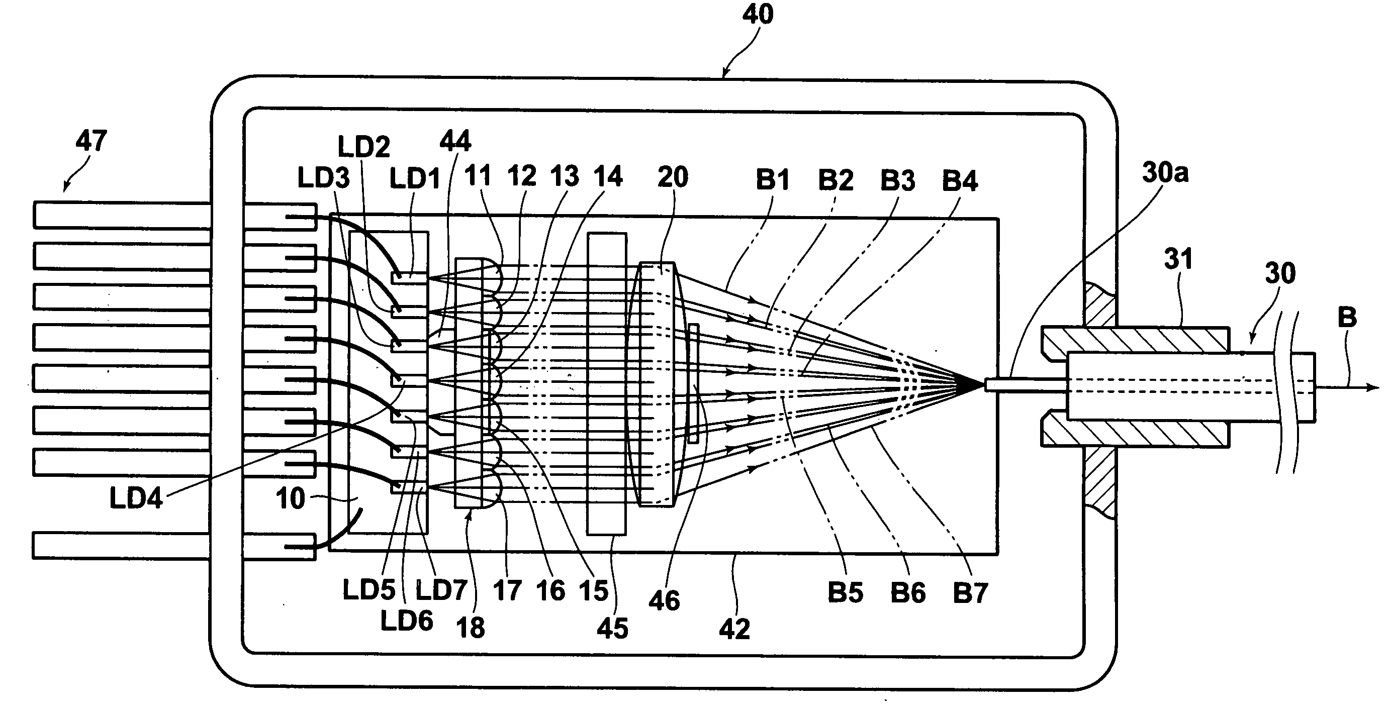
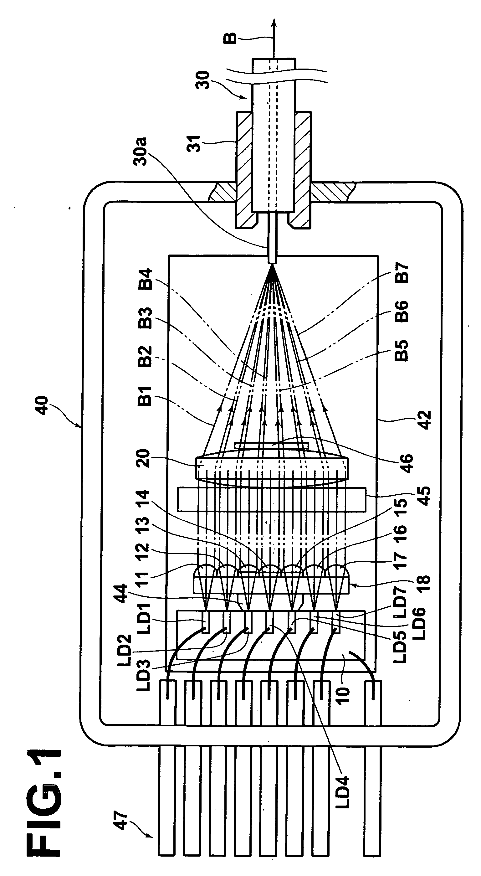
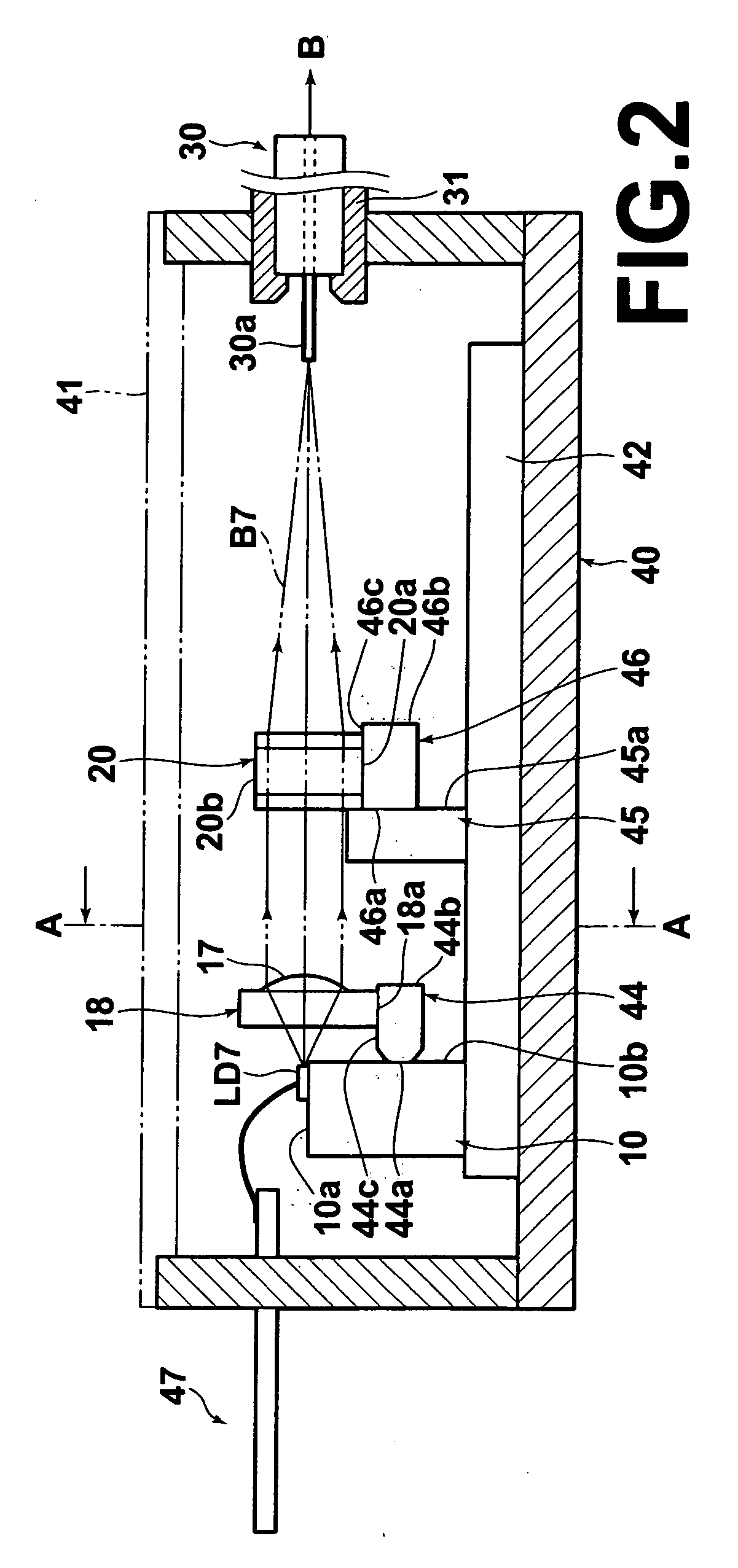
[0066]FIGS. 1, 2, and 3 are a plan view, a side view, and a partial front view respectively of the UV high luminance beam combining laser unit according to the present invention. As shown in the drawings, the beam combining unit includes, for example, 7 chip state transverse multimode GaN semiconductor lasers LD1, LD2, LD3, LD4, LD5, LD6, and LD7 fixedly disposed on a heat block 10 having a high thermal conductivity; a collimating lens array 18 constituted by integrally formed collimating lenses 11, 12, 13, 14, 15, 16, and 17, each corresponding to each of the lasers LD1, LD2, LD3, LD4, LD5, LD6, and LD7; a single condenser lens 20; and a single multimode optical fiber 30.

[0067] The GaN semiconductor lasers LD1 to LD7 oscillate at wavelengths in the range of 400 nm to 410 nm with an output power of around 200 mW. These GaN semiconductor lasers LD1 to LD7 constitute a laser array having 7 luminous points. In the present embodiment, single mode lasers are used as the GaN semiconductor...

second embodiment

[0117] In the second embodiment, a collimating lens holder 144 with the collimating lens array 18 fixedly bonded on the upper surface 144c thereof is fixedly bonded on the base plate 42 serving as the reference member directly instead of the heat block 10.

[0118] In the present embodiment, the collimating lens holder 144 is also formed such that the length of the upper surface 144c for bonding the collimating lens array 18 in the direction orthogonal to the optical axis direction of the lens (in the left-right direction in the drawing) is longer than the length of the lower surface 144d to be bonded to the base plate 42 in the same direction as shown in FIG. 9. Thus, the former length may be set long enough to improve the face alignment accuracy with the collimating lens array 18. On the other hand, the latter length may be set appropriately short within a range which ensures the bonding strength to minimize the strain that may occur at the bonded section with the base plate 42 due t...


PUM


Abstract

In a laser array unit in which a plurality of laser beams emitted from a laser array is received by a lens array, the lens holder for fixedly bonding the lens array is formed such that the length of the surface on which the lens array is bonded in the direction orthogonal to the optical axis direction of the lens is longer than the length of the surface to be bonded to a certain other fixing member in the same direction.

Description

BACKGROUND OF THE INVENTION [0001] 1. Field of the Invention [0002] The present invention relates to a lens holder to be fixedly bonded to a certain other fixing member after a lens array or an elongated lens is fixedly bonded thereto. The present invention also relates to a laser array unit using such lens holder. [0003] 2. Description of the Related Art [0004] A laser unit in which a plurality of laser beams are inputted to a single fiber to combine the beams in order to obtain a high power laser beam is known as described, for example, in U.S. Pat. No. 6,995,912 and Japanese Unexamined Patent Publication No. 2004-134641. The laser unit is basically constituted by a semiconductor laser array (which may be an integrated unit or constituted by a plurality of discrete elements) having a plurality of luminous points to emit a plurality of laser beams; a single optical fiber; and a condensing optical system for condensing and coupling the plurality of laser beams emitted from the semic...

Claims


Application Information

Patent Timeline
Patent Type & Authority Applications(United States)
IPC IPC(8): H01S3/08
CPCG02B3/0006G02B7/025G02B27/0961H01S5/005H01S5/02208H01S5/02248H01S5/4031H01S5/02284H01S5/02292H01S5/02469H01S5/32341H01S5/4012H01S5/02272H01S5/02251H01S5/02255H01S5/02325H01S5/0237
Inventor TERAMURA, YUICHINAGANO, KAZUHIKO
Owner ADTEC ENG
Why Eureka
Try Eureka