
Inspection microchip and inspection device using the chip

a microchip and inspection device technology, applied in the field of microchip inspection, can solve the problems of increased cost, complicated structure, and complicated manufacturing steps, and achieve the effects of simple structure, reduced manufacturing cost, and high reliability

Inactive Publication Date: 2006-10-05
KONICA MINOLTA MEDICAL & GRAPHICS INC
View PDF1 Cites 0 Cited by
  • Summary
  • Abstract
  • Description
  • Claims
  • Application Information

AI Technical Summary

Benefits of technology

[0026] The present invention was developed in view of the foregoing situation and is intended to provide a highly reliable inspection microchip which has a reverse flow prevention structure composing a reverse flow prevention section for preventing reverse flow of a liquid at a joining section where two flow paths of the inspection microchip join, requires no separate drive mechanism, uses a simple structure, causes no enlargement of inspection microchip, reduces the manufacturing cost, surely prevents reverse flow of a liquid, and executes accurate inspection, as well as an inspection device using it.

Problems solved by technology

Further, in the check valve shown in FIG. 10(a), it is necessary to use a minute sphere 167 as a valve element, form an opening 168 in the flow path, and arrange the minute sphere 167 in it, so that the constitution is complicated, and the manufacturing steps are also complicated, and the cost is increased.
Further, also in the check valve shown in FIG. 10(b), it is necessary to form a elastic substrate 169 which is laminated on the substrate 162 and is equipped with an end extended above the opening 168, so that the constitution is complicated, and the manufacturing steps are also complicated, and the cost is increased.
Furthermore, in the active valve shown in FIG. 11, it is necessary to arrange a elastic substrate 163 equipped with a valve section 164 projected downward and compress the elastic substrate 163 from above by valve element transforming means such as air pressure, oil pressure, a hydraulic piston, a piezo-electric actuator, and a shape memory alloy actuator, so that a drive mechanism is necessary separately, and the constitution is complicated, and the manufacturing steps are also complicated, and the cost is increased, as well as the inspection microchip is made larger.
Furthermore, as shown in FIGS. 12 and 13, it is necessary to arrange a bimetal 181 and a shape memory alloy 182 and transform them by power supply and heating, so that a power supply mechanism is necessary separately, and the constitution is complicated, and the manufacturing steps are also complicated, and the cost is increased, as well as the inspection microchip is made larger.

Method used


Image

  • Inspection microchip and inspection device using the chip
  • Inspection microchip and inspection device using the chip
  • Inspection microchip and inspection device using the chip

Examples


Embodiment Construction

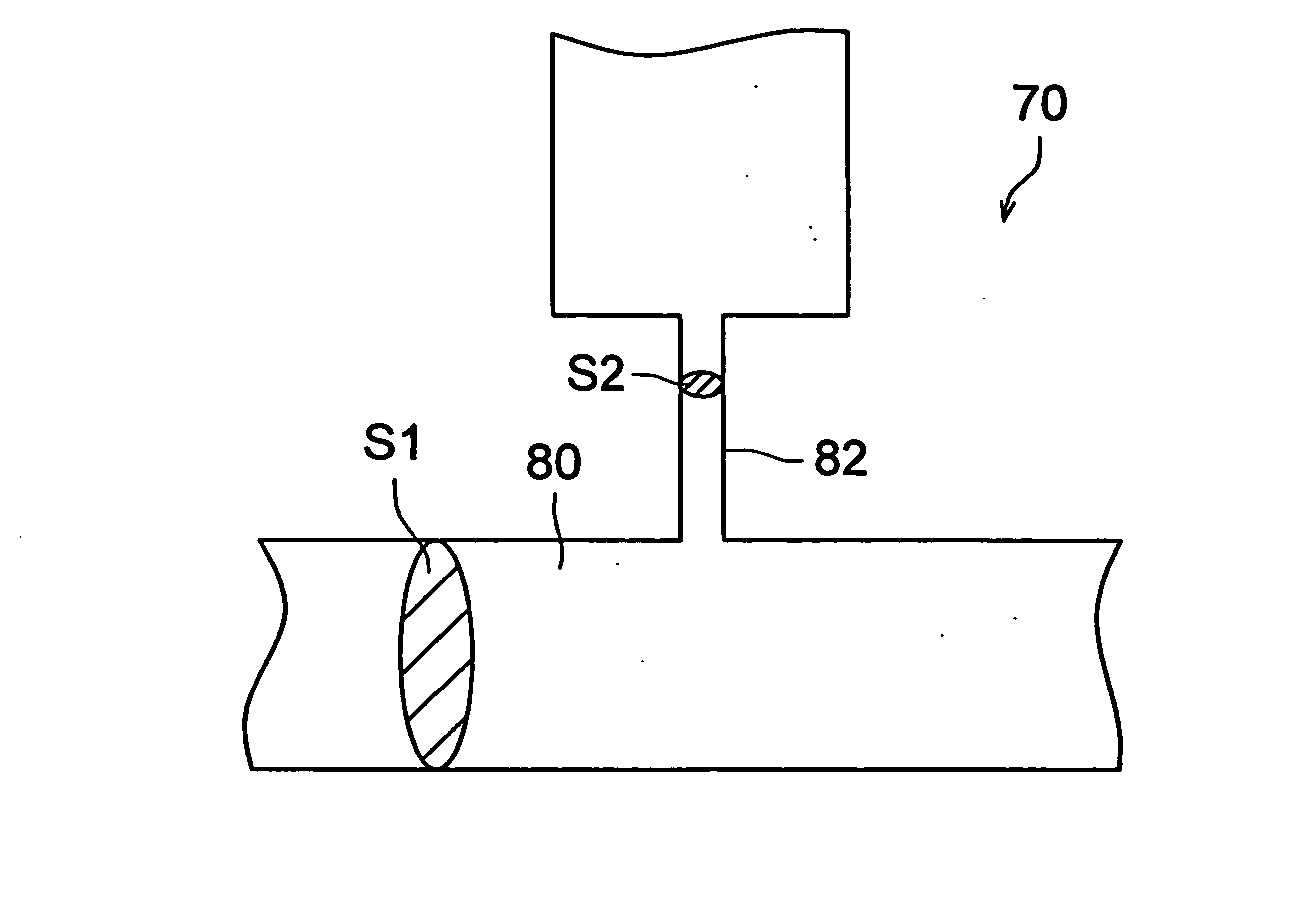
[0054] In one flow path for preventing reverse flow like this, the flow path resistance on the upstream side of the reverse flow preventing means is set so as to be larger than the overall flow path resistance which is the total of the upstream and downstream flow path resistances of the joining section in the other flow path.

[0055] Therefore, when feeding a liquid to be fed from the other flow path to the joining flow path, the flow path resistance of the reverse flow preventing means is set larger than the overall flow path resistance which is the total of the upstream and downstream flow path resistances of the joining section in the other flow path, so that the liquid can be surely prevented from reversely flowing into another flow path on the upstream side of the reverse flow preventing means.

[0056] Further, when feeding a liquid to be fed from one flow path to the joining flow path, the liquid is fed at a pump pressure sufficiently high to supplement a pressure drop due to t...


PUM


Abstract

At the joining section where two flow paths join, a reverse flow preventing means is installed in one flow path on the upstream side of the joining section and the flow path resistance of the reverse flow preventing means is set so as to be larger than the overall flow path resistance which is the total flow path resistance of the upstream and downstream sides of the joining section in the other flow path.

Description

[0001] This application is based on Japanese Patent Application No. 2005-103522 filed on Mar. 31, 2005 in Japanese Patent Office, the entire content of which is hereby incorporated by reference. BACKGROUND OF THE INVENTION [0002] This invention relates to a microchip for inspection that can be used as a micro-reactor in gene screening for example, and to an inspection device which uses this microchip. [0003] In recent years, due to the use of micro-machine technology and microscopic processing technology, systems are being developed in which devices and means for example pumps, valves, flow paths, sensors and the like, for performing conventional sample preparation, chemical analysis, chemical synthesis and the like are caused to be ultra-fine and integrated on a single chip. [0004] These systems are called μ-TAS (Micro Total Analysis System), bioreactor, lab-on-chips, and biochips, and much is expected of their application in the fields of medical testing and diagnosis, environment...

Claims


Application Information

Patent Timeline
Patent Type & Authority Applications(United States)
IPC IPC(8): B01L3/00
CPCB01F5/0646F16K2099/0084B01F13/0059B01L3/50273B01L3/502738B01L3/502746B01L2300/0816B01L2300/0867B01L2400/0487B01L2400/0605B01L2400/084C08L2201/12F16K99/0001F16K99/0007F16K99/0017F16K99/0023F16K99/0038F16K99/0044F16K99/0048F16K99/0057F16K99/0059F16K2099/008B01F5/0647B01F25/4331B01F25/433B01F33/30
Inventor HIGASHINO, KUSUNOKINAKAJIMA, AKIHISASANDO, YASUHIRO
Owner KONICA MINOLTA MEDICAL & GRAPHICS INC
Learn More