Electrochemical removal of die coatings

a technology of electrochemical removal and die coating, which is applied in the direction of electrolysis components, printed circuit manufacturing, manufacturing tools, etc., can solve the problems of large tooling cost, failure locally, and loss at the end of service life, and achieve the effect of reducing the cost of frequent discarding and replacement of used substrates

Inactive Publication Date: 2006-10-12
COLORADO SCHOOL OF MINES
View PDF11 Cites 11 Cited by
  • Summary
  • Abstract
  • Description
  • Claims
  • Application Information

AI Technical Summary

Benefits of technology

[0007] The present invention is directed to a method and an apparatus for the electrochemical removal of coatings from metallic substrates, such as tools or dies. The present invention, for example, enables the resurfacing, recoating, and even repair of used metallic substrates, such as tools or dies, thereby greatly diminishing the costs associated with frequent discarding and replacement of the used substrates.

Problems solved by technology

These coatings, however, can fail locally during use or due to mishandling, or may be lost at the end of the service life due to stress, lack of adhesion and / or wear.
This represents an enormous tooling cost as most of the discarded tools and dies are high alloy steels and other non-ferrous, expensive super-alloys.
This technique is, however, slow and requires specialized tooling.
However, CMP is of limited use for the removal of coatings on non-planar surfaces.

Method used


Image

  • Electrochemical removal of die coatings
  • Electrochemical removal of die coatings
  • Electrochemical removal of die coatings

Examples


example 1

TiAlN Coatings

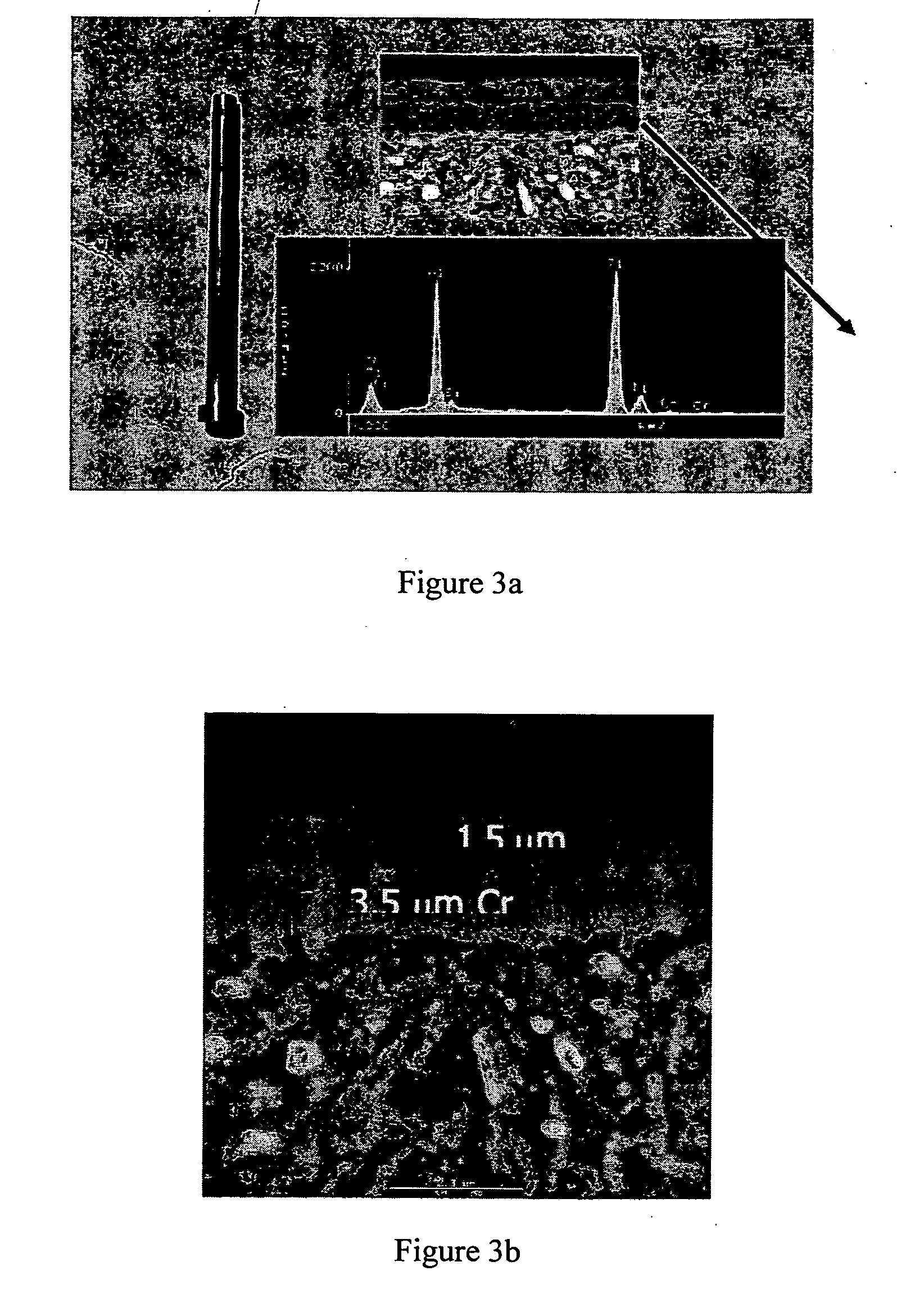
[0047] A coating of 1.5 mm of graded TiN / TiAlN over 3.5 mm e-Cr (as shown in FIGS. 3a 3b) was dissolved in both an aqua-regia and a sodium hydroxide electrolyte solution. FIG. 4 shows the sample after exposure to aqua-regia (3:1 HCl—HNO3) for 2 hours at 50° C. The figure shows that the coating was been severely attacked and local pitting caused dissolution of the substrate. The acid concentration was decreased to 50% and further to 10%. The test temperature was lowered to 30° C. The diluted acid still pitted the substrate at lower temperatures as shown in FIGS. 5a-5b. FIGS. 5a-5b depict a magnified image of core pins following exposure to HCl—HNO3; (a) 50% acid after 1 hour and, (b) 10% acid after 2 hours.

[0048] The electrolytic solution was changed to 0.1 M sodium hydroxide and chemical dissolution was conducted for various lengths of time at different temperatures. In each trial, the electrolyte solution was stirred and the samples were rotated. FIG. 6a shows the o...

example 2

CrC Coatings

[0049] A coating of approximately 7.5 mm of chromium carbide on a drill bit is shown in FIG. 7. For the removal of chromium carbide, a basic solution of 0.1 M NaOH was used as the electrolyte and a temperature of 80° C. was used under the same configuration of electrode stirring described in Example 1. Platinum wire was used as the cathode and the coated drill bit served as the anode. FIG. 8 shows the drill bit after complete removal of coating. To further optimize the removal process, the electrolyte temperature was dropped to 50° C. and further to about 25° C. (ambient temperature). It was found that the coating could be removed in a time between about 5 minutes to about 90 minutes duration depending on the temperature. FIG. 9 shows the clean surface prepared at room temperature. The surface profile shows that the substrate had not been affected. FIG. 10 indicates that the cutting edge of the drill bit was still sharp. No evidence of local attack or pitting was seen o...


PUM

PropertyMeasurementUnit
temperatureaaaaaaaaaa

Abstract

Methods of uniformly removing coatings from metallic substrates, such as tools and dies, without damaging the surface of the underlying substrate are provided. The processes are optimized for steel substrates with metallic carbide or nitride coatings. The methods encompass aqueous electrochemical removal using stirred, low temperature, basic electrolytes. Following removal of an old coating, a new coating may be applied, allowing recycle and reuse of the underlying metal substrate. The ability to recoat and reuse tools represents a significant cost savings.

Description

CROSS REFERENCE TO RELATED APPLICATION [0001] This application claims the benefit of priority under 35 U.S.C. § 119(e) to U.S. Provisional Patent Application Ser. No. 60 / 662,756, filed Mar. 16, 2005, which is incorporated herein in its entirety by this reference.FIELD OF THE INVENTION [0002] The present invention relates to the removal of coating materials, and more particularly to the electrochemical removal of a coating from a metallic substrate. BACKGROUND OF THE INVENTION [0003] Hard ceramic coatings impart specific tribological properties to metallic components and instruments such as machining tools, die core-pins, and high temperature devices. These hard coatings impart wear and abrasion resistance, reduce friction, enhance oxidation and corrosion resistance, and impart chemical inertness to the metal components to which they are applied. These protective mechanisms prolong the service life of tools while improving tool performance and reducing tooling costs. These coatings, ...

Claims


Application Information

Patent Timeline
Patent Type & Authority Applications(United States)
IPC IPC(8): B23H3/00
CPCC25F5/00
Inventor MISHRA, BRAJENDRAMOORE, JOHN J.MATTERSON, JOE
Owner COLORADO SCHOOL OF MINES
Why Eureka
Try Eureka