Reversing motor windshield wiper system

Inactive Publication Date: 2006-10-12
INTIER AUTOMATIVE CLOSURES INC
View PDF27 Cites 39 Cited by
  • Summary
  • Abstract
  • Description
  • Claims
  • Application Information

AI Technical Summary

Benefits of technology

[0014] Another aspect of the invention relates to a system for detecting the angular position of a motor having a rotating output shaft. The system includes a multipole magnet mounted on the output shaft and two digital Hall effect sensors mounted about the shaft to sense variations in magnetic field. The sensors generate pulse trains which are fed, respectively, to at least two pulse-width counters. One counter has a faster prescaler than the other. At high rpm the rotational speed of the motor is measured based on the output of the counter with the faster prescaler and at low rpm the rotational speed of the motor is measured based on the output of the other counter. This facilitates use of a low cost counter or micro-controller whilst avoiding the problem of counter overrun errors.
[0015] Another aspect of the invention relates to a system for detecting the angular position of a motor having a rotating output shaft. This system includes a multipole magnet mounted on the output shaft and analog and digital Hall effect sensors mounted about the shaft to sense variations in magnet

Problems solved by technology

Reversing wiper motor systems face a number of technical issues.
This system is not preferred because it employs a mechanically-actuated position detecting means which is prone to fatigue and corrosion.
The problem with such a system is its lack of flexibility, since the wipe angle will remain fixed and cannot be adjusted on the fly to compensate for environmental conditions such as wind speed, nor can the system be readily implemented in other vehicles which require diff

Method used


Image

  • Reversing motor windshield wiper system
  • Reversing motor windshield wiper system
  • Reversing motor windshield wiper system

Examples


Example

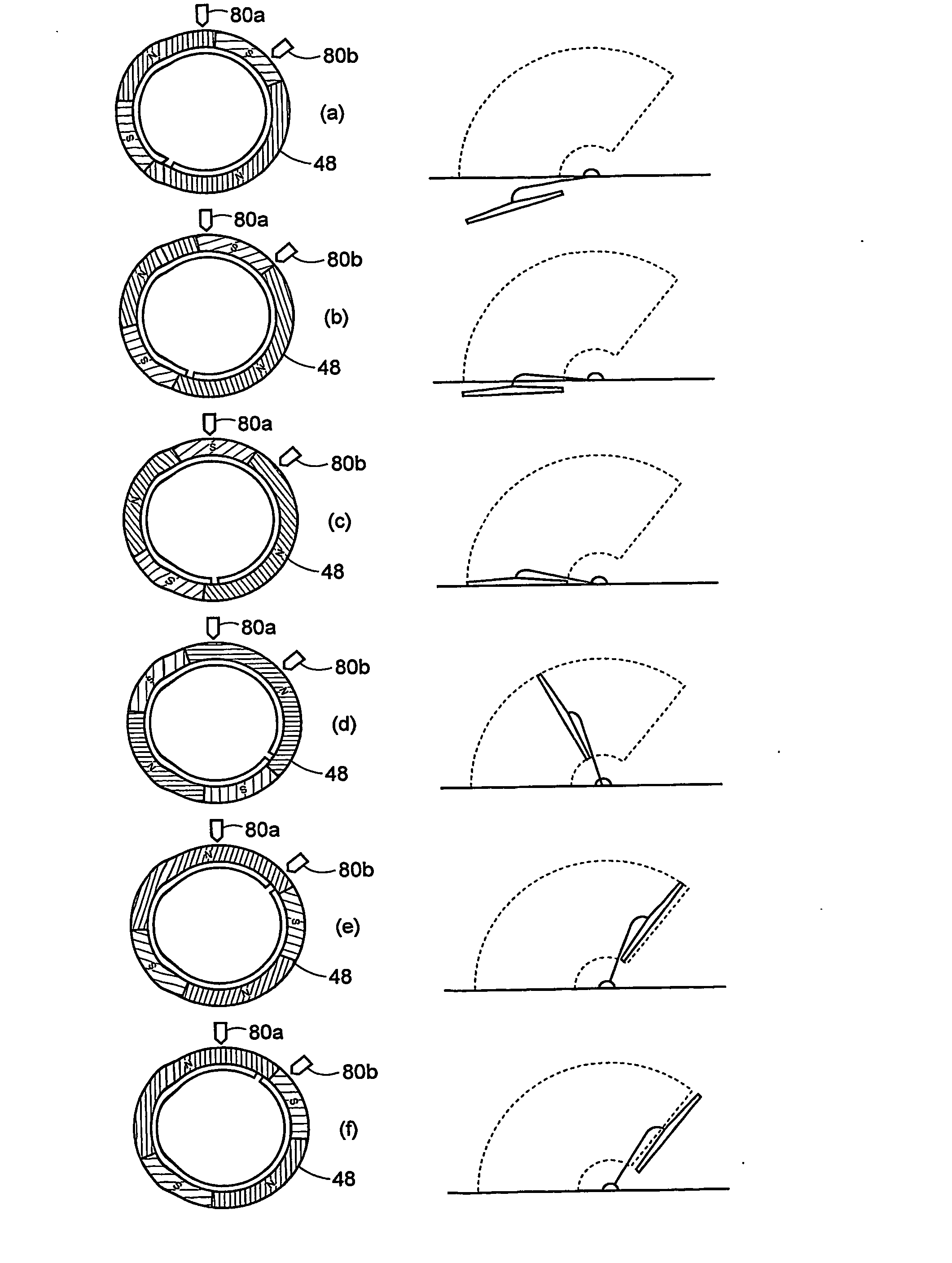
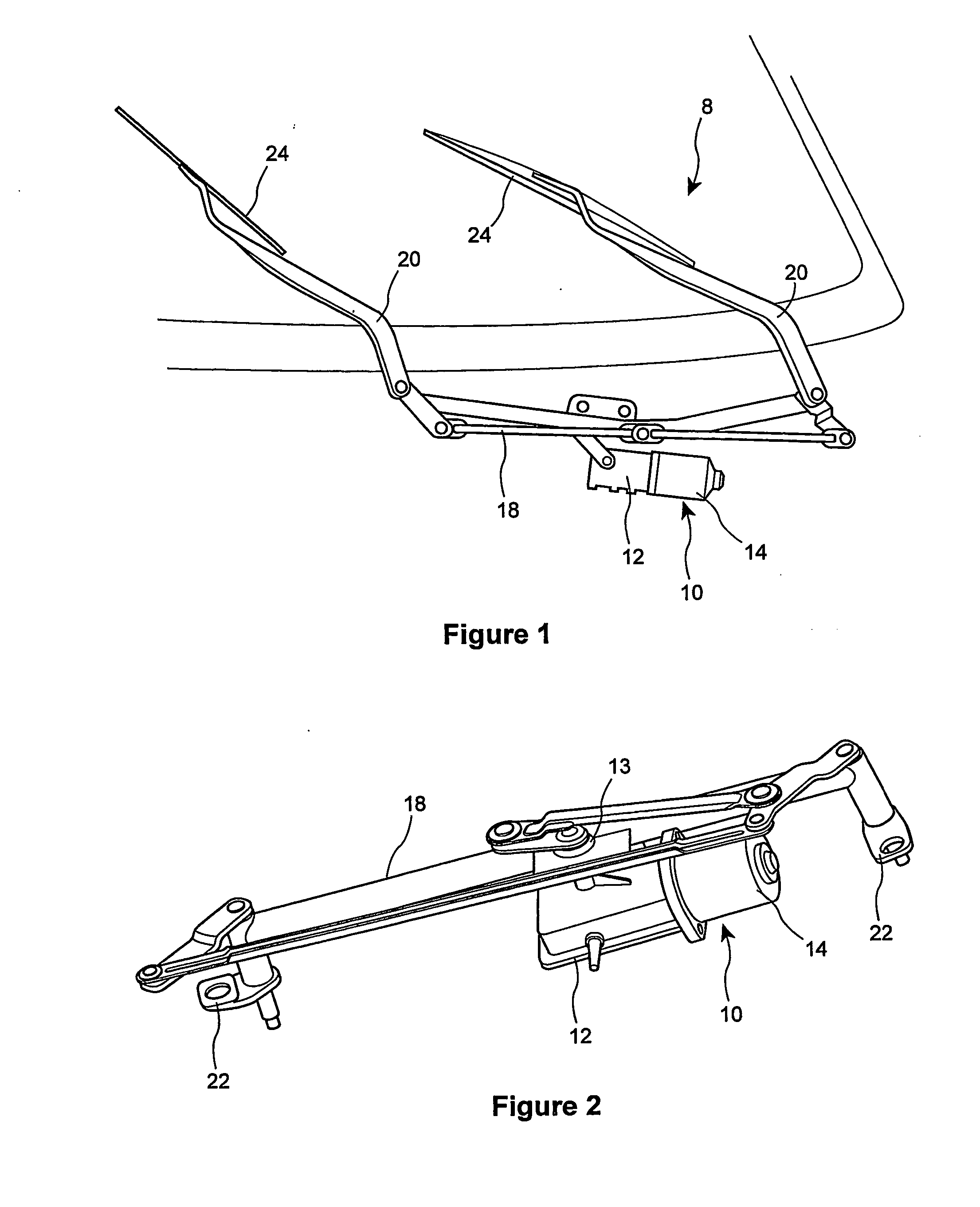
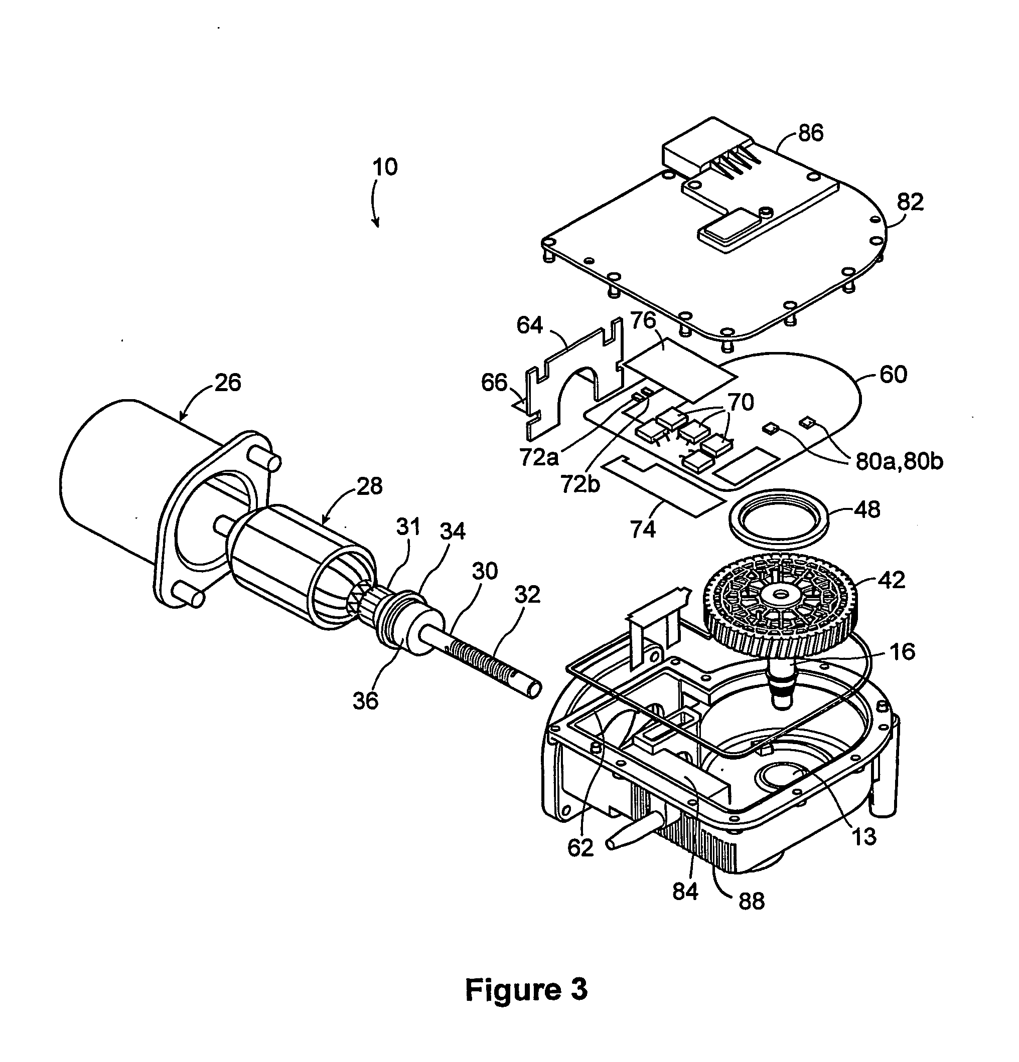
[0033]FIGS. 1 and 2 show a reversing-motor windshield wiper system 8 including a wiper power unit 10 constructed according to the preferred embodiment. The power unit 10 comprises a drive motor 14 connected to a gearbox housing 12. Referring additionally to the exploded view of the power unit 10 in FIG. 3, the housing 12 includes an outlet 13 for an output shaft 16 which drives a linkage 18 onto which two wiper arms 20 are mounted (at mounts 22). The linkage 18 drives the two wiper arms 20 (FIG. 1), each of which carries a wiper blade 24. The invention may employ conventional linkage mechanisms as known in the art per se. As described in greater detail below, the motor 14 is controlled to rotate in different angular directions in order to oscillate the wiper arms 20 across the windshield.

[0034] As shown in FIG. 3, the motor 14 comprises a stator 26 and a rotor 28, which is shown in isolation in FIG. 4. The constructional details of the motor 14 are not important to the invention an...


PUM


Abstract

A reversing wiper motor system has a first detector including a detectant which rotates in synchronism with the wiper. The detector physically identifies a plurality of distinct angular zones across the entire range of motion of the wiper, including a wiper park zone, a wiping zone, and a wiper out-of-bound zone. A second detector detects incremental movement of the wiper within any given zone. Control circuitry controls the direction of the motor based on the detected zone and the incremental motion of the wiper therein. The system enables the wiper to be located upon power-up.

Description

FIELD OF INVENTION [0001] The invention generally relates to the art of motor control systems and more specifically to the field of reversing-motor windshield wiper systems. BACKGROUND OF INVENTION [0002] Windshield wiper systems in which the wiper motor reverses direction in order to oscillate or reciprocate the windshield blades are known in the art. Examples of such systems are disclosed in WIPO Publication No. WO 95 / 33638, WIPO Publication No. WO 98 / 07601, U.S. Pat. No. 6,249,098, and US Publication No. 2002 / 0030458. [0003] Reversing wiper motor systems face a number of technical issues. One of these relates to position-determining means. In order to accurately control the wipers, it is desirable to ascertain the angular position and velocity of the wiper motor and / or associated gears with a relatively high degree of precision. The prior art presents various means for accomplishing this objective. For example, the system disclosed in U.S. Pat. No. 6,249,098 to Miyazaki et al. em...

Claims


Application Information

Patent Timeline
IPC IPC(8): H02P7/00B60SB60S1/08B60S1/16B60S1/44
CPCB60S1/08Y10S318/02B60S1/166
Inventor MARENTETTE, LESLIE
Owner INTIER AUTOMATIVE CLOSURES INC
Why Eureka
Try Eureka