Modular wireless test architecture and method

Active Publication Date: 2006-10-12
AZIMUTH SYSTEMS
View PDF14 Cites 73 Cited by
  • Summary
  • Abstract
  • Description
  • Claims
  • Application Information

AI Technical Summary

Benefits of technology

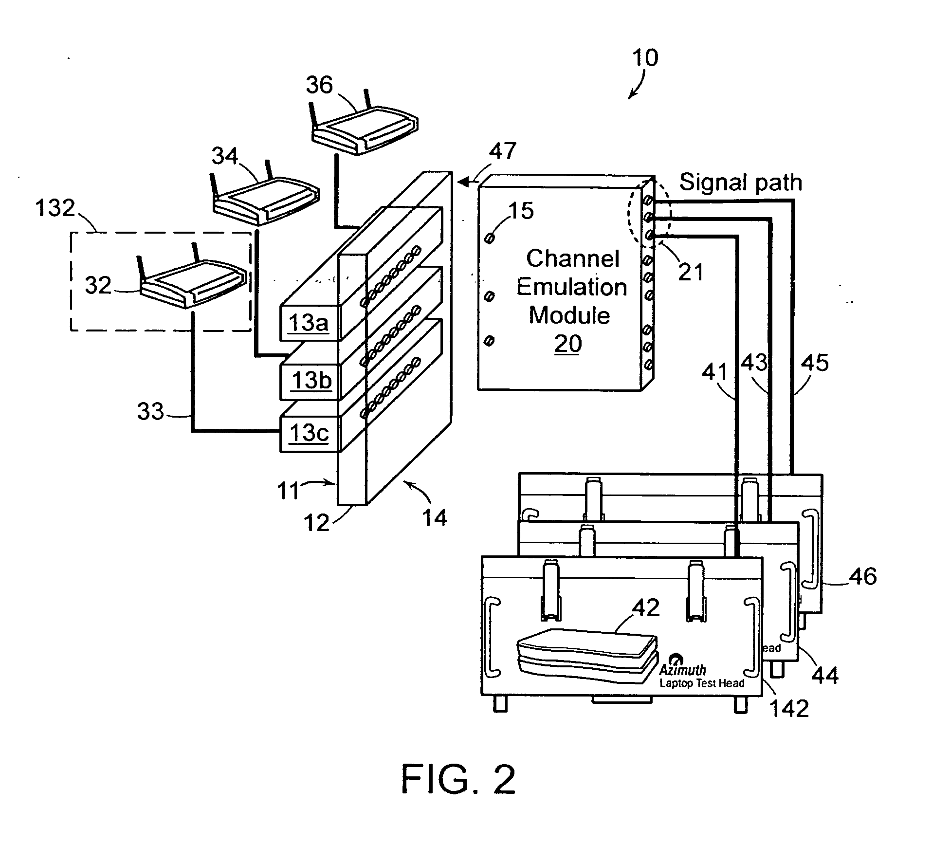
[0011] The channel emulator module is thus an interchangeable component of a modular wireless network test architecture that enables testing of a wide range of wireless protocols and network topologies. The modular nature of the RF combiners and the channel emulator modules makes it easy to change test network configuration by simply adding or removing the combiners and modules on either side of the backplane.
[0013] According to another aspect of the invention, the test module includes a latency measurement method and apparatus, which applies time stamps to frames as they are transmitted and received at various network interfaces of the test module. Time stamping frames as they are transmitted and received reduces nondeterministic delay in the measurement process, thereby increasing the accuracy of the latency measurement.

Problems solved by technology

Because the costs associated with developing, purchasing, selling and deploying a new wireless technology are often quite high, it is common to conduct testing to mitigate the risk that the technology will fail to perform as planned.
However, wireless devices are notoriously difficult to test because they can be affected by ambient sources of interference.
Further, the conditions to which a wireless device may be subjected in actual use are so great in number that it is difficult and time-consuming to create all of those conditions in a test environment.
However, this technique is too labor-intensive and imprecise to simulate a wide variety of traffic conditions, distances between access points and rates of motion in a practical manner.
Further, such a manual, open-air test can be rendered invalid by transient interference from a microwave, RADAR or other RF source.
While this architecture is effective for simulating movement within the topology, the simulation of multi-dimensional movement is restricted by the available connections.
The reflections arrive at a receiver with unpredictable amplitude, time and phase relationships, causing multipath distortion of the original signal.
High data-rate signals are more susceptible to multipath, which has traditionally limited speed and range.
The higher the data rate, the more detrimental the multipath distortion is to the signal.

Method used


Image

  • Modular wireless test architecture and method
  • Modular wireless test architecture and method
  • Modular wireless test architecture and method

Examples


embodiment 195

[0062] Referring now to FIG. 10, an illustration a first analog embodiment 195 of the channel emulator component is shown. The channel emulator 195 adds channel effects to the bi-directional signals exchanged between the backplane and the RF ports 21 of the channel emulator module. For purposes only of facilitating understanding of the below description, the term ‘forward’ path shall be used to describe transmissions on a path originating at the backplane and ending at the RF Ports 21, and the term ‘reverse path’ will be used to describe transmissions on a path originating at the RF Ports 21 and directed at the backplane. The illustrated embodiment shows circuitry that may be included to add multipath to each one of N paths included in an N×M multipath transmission channel under test. The RF channel emulator 195 includes a splitter / combiner 73 coupled to a plurality of delay lines 75 and a plurality of programmable attenuators 76. The delay lines are coupled to a splitter / combiner 7...

embodiment 495

[0067] Referring now to FIG. 13, an embodiment 495 of an RF channel emulator is shown wherein the reverse path circuitry is similar to the forward path circuitry described in FIG. 12. Thus in the reverse path a second RF to IF down converter 244 is provided for converting received RF signals from circulator 222 to the mixer that down-converts the RF signal to IF, a DSP engine 242, an IF to RF up-converter 240 and programmable attenuation 245. DSP engine 242 and attenuation 245 are independently programmable and thereby allow different characteristics to be modeled on the return path.

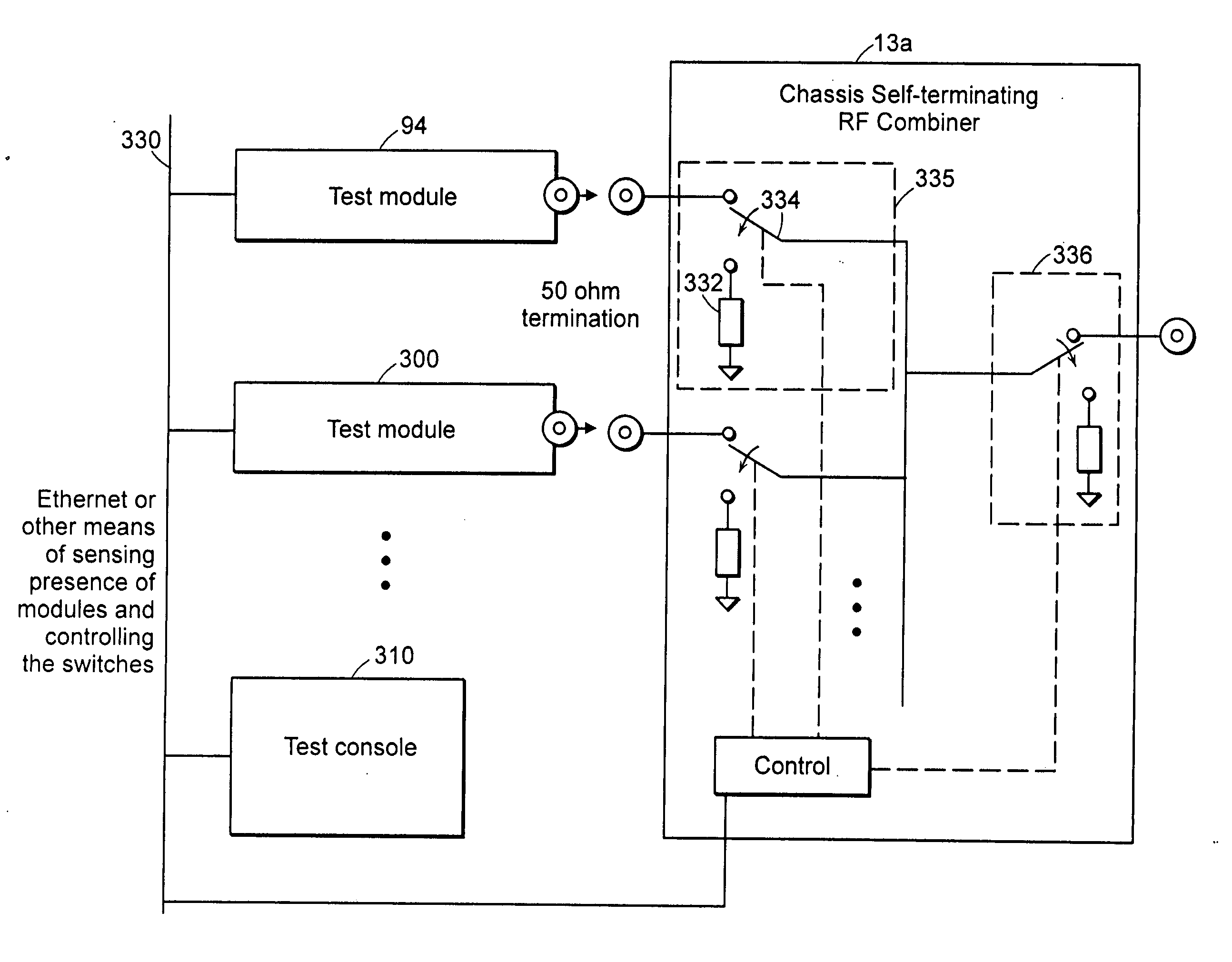
[0068] One example of how the MIMO channel emulation modules may be used in a test environment is shown in FIG. 14. In FIG. 14 the test bed includes two MIMO channel emulation modules 94 and 96. MIMO access point DUT antenna ports are coupled to the RF ports of each of the modules 94, and 96, and a MIMO client DUT 78 is coupled to RF combiners 13a-13c. A variety of channel effects, including multipath, p...


PUM


Abstract

A modular test chassis for use in testing wireless devices includes a backplane and a channel emulation module coupled to the backplane. The channel emulation module comprises circuitry for emulating the effects of a dynamic physical environment (including air, interfering signals, interfering structures, movement, etc.) on signals in the transmission channel shared by the first and second device. Different channel emulation modules may be included in the test system depending upon the protocol, network topology or capability under test. A test module may be provided to generate traffic at multiple interfaces of SISO or MIMO DUTs to enable thorough testing of device and system behavior in the presence of emulated network traffic and fault conditions. A latency measurement system and method applies timestamps frames as they are transmit and received at the test module for improved latency measurement accuracy.

Description

RELATED APPLICATIONS [0001] This application claims priority under 35 U.S.C. §119(e) to provisional patent application Ser. No. 60 / 670,522 filed Apr. 12, 2005 by Mlinarsky and Wright, incorporated herein by reference.FIELD OF THE INVENTION [0002] This invention relates generally to the field of test equipment, and more particularly to an improved architecture for use in testing wireless devices. BACKGROUND OF THE INVENTION [0003] New wireless technology is being developed and deployed to provide support for voice and multimedia services in both residential and enterprise environments. Wireless Local Area Network (“WLAN”) devices, for example, are being developed in conjunction with IEEE 802.11 standards to support packetized voice communications such as Voice over Internet Protocol (“VoIP”). There are technological hurdles that must be overcome in order to support voice and multimedia on WLANs because the technology was initially designed to support simple data communications. In pa...

Claims


Application Information

Patent Timeline
IPC IPC(8): H04B17/00
CPCH04B17/391
Inventor MLINARSKY, FANNYWRIGHT, CHARLES R.
Owner AZIMUTH SYSTEMS
Why Eureka
Try Eureka