Prismatic lithium secondary battery

a lithium secondary battery and lithium-ion battery technology, applied in the direction of cell components, final product manufacturing, sustainable manufacturing/processing, etc., can solve the problems of internal short circuit, overheating of the battery, shrinkage of the separator made of a micro-porous film, etc., and achieve excellent battery characteristics and safety.

Active Publication Date: 2006-10-19
PANASONIC CORP
View PDF4 Cites 37 Cited by
  • Summary
  • Abstract
  • Description
  • Claims
  • Application Information

AI Technical Summary

Benefits of technology

[0006] It is therefore an object of the present invention to prevent a breakage of the porous heat-resistant layer and provide a prismatic lithium secondary battery that is excellent in both safety and battery characteristics.
[0016] The present invention is based on the above two findings. The present invention proposes controlling the force of the main flat portions of side wall of the battery can which pushes back the porous heat-resistant layer in an appropriate range, depending on the thickness of the porous heat-resistant layer. Accordingly, it is possible to prevent the porous heat-resistant layer from breaking and ensure safety in the event of internal short-circuits. Further, it is also possible to realize excellent battery characteristics.

Problems solved by technology

However, when a lithium secondary battery is stored in an environment at extremely high temperatures for an extended period of time, its separator made of a micro-porous film tends to shrink.
If the separator shrinks, then the positive electrode and the negative electrode may physically come into contact with each other to cause an internal short-circuit.
Once an internal short-circuit occurs, the short-circuit may expand due to Joule's heat generated by the short-circuit current, thereby resulting in overheating of the battery.
Therefore, the electrode assembly is distorted, and the porous heat-resistant layer may break since the amount of the binder contained in the porous heat-resistant layer is relatively small and the bonding between filler particles is weak.
In such cases, the function of the porous heat-resistant layer of suppressing the overheating of the battery in the event of an internal short-circuit is impaired.

Method used


Image

  • Prismatic lithium secondary battery
  • Prismatic lithium secondary battery
  • Prismatic lithium secondary battery

Examples


example 1

(Battery 1)

(i) Preparation of Positive Electrode

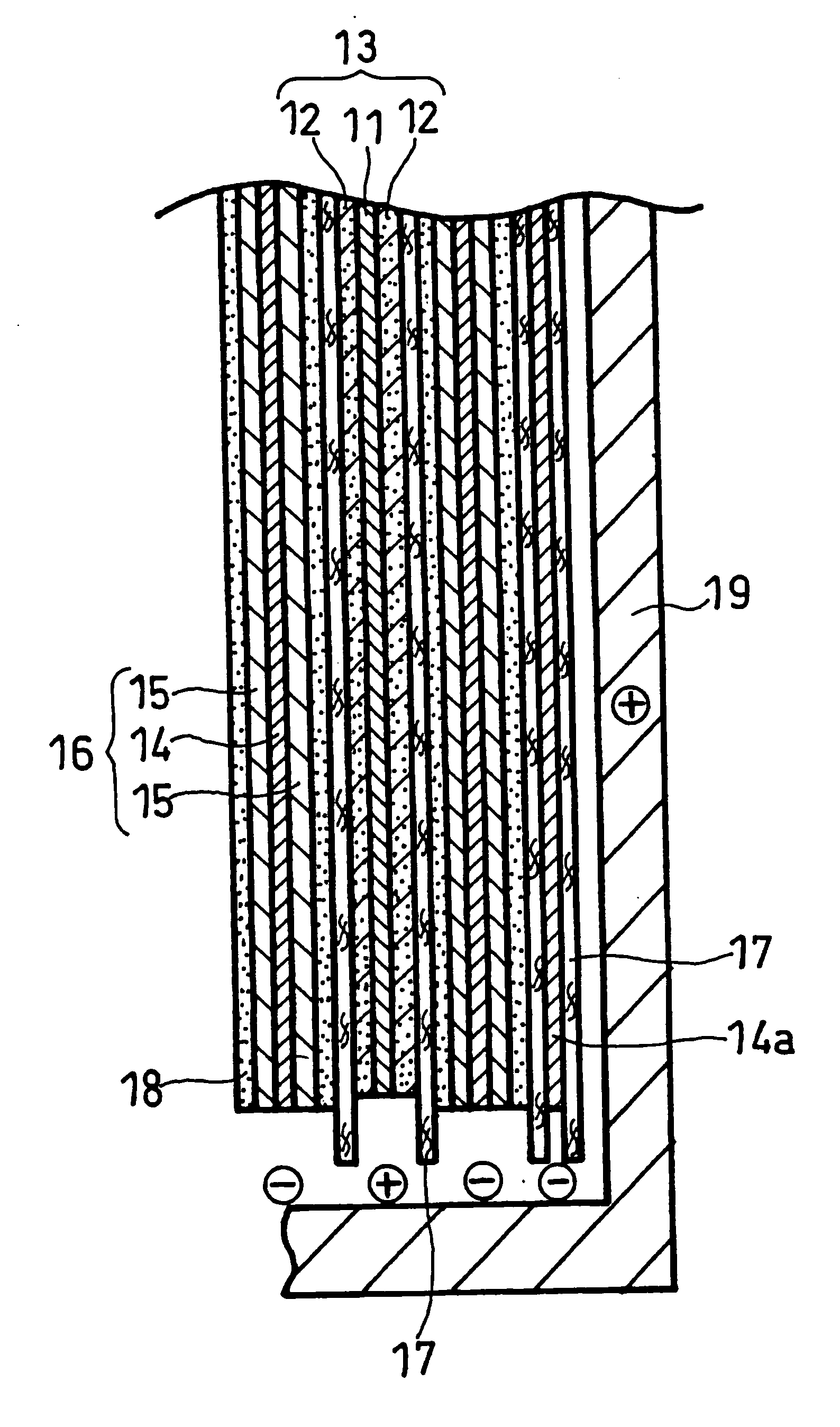
[0043] A positive electrode mixture paste was prepared by stirring 3 kg of lithium cobaltate, 1 kg of PVDF#1320 available from KUREHA CORPORATION (N-methyl-2-pyrrolidone (hereinafter referred to as NMP) solution containing 12% by weight of PVDF), 90 g of acetylene black, and a suitable amount of NMP with a double-arm kneader. This paste was applied onto both sides of a positive electrode core member comprising a 15-μm-thick aluminum foil, dried, and rolled, to form a positive electrode with positive electrode active material layers. This positive electrode had a total thickness of 130 μm. The positive electrode was cut to a strip with a width of 43 mm.

(ii) Preparation of Negative Electrode

[0044] A negative electrode mixture paste was prepared by stirring 3 kg of artificial graphite, 75 g of BM-400B available from Zeon Corporation (aqueous dispersion containing 40% by weight of modified styrene butadiene rubber), 30 g of CMC, and...


PUM

PropertyMeasurementUnit
thicknessaaaaaaaaaa
thicknessaaaaaaaaaa
thicknessaaaaaaaaaa

Abstract

A prismatic lithium secondary battery includes: a prismatic battery can having a bottom, a side wall, and an open top; an electrode assembly; a non-aqueous electrolyte; and a sealing plate covering the open top of the battery can that accommodates the electrode assembly and the non-aqueous electrolyte. The electrode assembly includes: a positive electrode; a negative electrode; and a porous heat-resistant layer and a separator that are interposed between the positive and negative electrodes. The side wall of the battery can has two rectangular main flat portions that are opposed to each other, and the thickness A of the porous heat-resistant layer and the thickness B of each of the main flat portions of the side wall satisfy the relation: 0.003≦A / B≦0.05.

Description

FIELD OF THE INVENTION [0001] The present invention relates to a prismatic lithium secondary battery that is excellent in both safety and battery characteristics. BACKGROUND OF THE INVENTION [0002] Lithium secondary batteries have received attention as high-capacity power sources for portable and other appliances. Further, lithium secondary batteries have recently been receiving attention as high-output power sources for electric vehicles and the like. Chemical batteries such as lithium secondary batteries usually have a separator that electrically insulates a positive electrode from a negative electrode and holds an electrolyte. In the case of a lithium secondary battery, a micro-porous film made of polyolefin (e.g., polyethylene, polypropylene, etc.) is mainly used as the separator. The electrode assembly of a prismatic lithium secondary battery is produced by winding the positive electrode, the negative electrode, and the separator interposed between the two electrodes such that ...

Claims


Application Information

Patent Timeline
Patent Type & Authority Applications(United States)
IPC IPC(8): H01M2/18H01M2/02H01M10/052H01M10/0587H01M10/36H01M50/103
CPCH01M2/0207H01M2/0217H01M2/1673Y02T10/7011H01M10/0587H01M10/4235Y02E60/122H01M10/052Y02E60/10H01M50/103H01M50/46Y02P70/50H01M10/0583H01M4/13Y02T10/70
Inventor FUJIKAWA, MASATOSUZUKI, KOHEIINOUE, KAORUSHIMADA, MIKINARI
Owner PANASONIC CORP
Why Eureka
Try Eureka