
Anode material for lithium secondary cell with high capacity

a secondary cell and anode material technology, applied in secondary cell details, cell components, electrochemical generators, etc., can solve the problems of not being used as a practical anode material for a lithium secondary cell, not having sufficient and acceptable cycle life characteristics, and poor cycle life characteristics of lithium cells, etc., to achieve excellent cycle life characteristics and high charge/discharge capacity

Active Publication Date: 2006-10-19
LG ENERGY SOLUTION LTD
View PDF10 Cites 65 Cited by
  • Summary
  • Abstract
  • Description
  • Claims
  • Application Information

AI Technical Summary

Benefits of technology

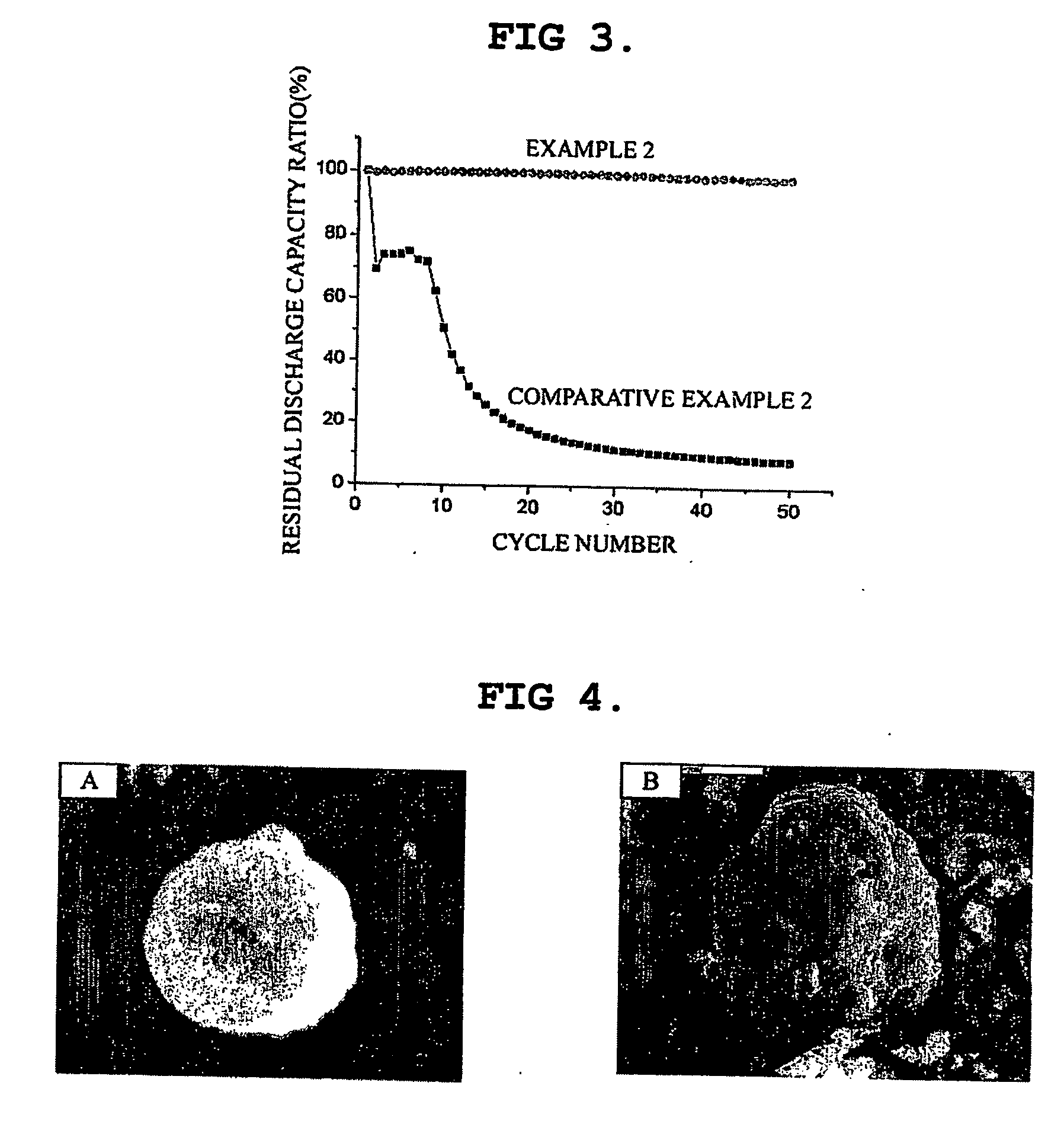
[0013] Therefore, the present invention has been made in view of the above-mentioned problems, and it is an object of the present invention to provide an anode material for a lithium secondary cell having a high charge / discharge capacity and excellent cycle life characteristics.
[0017] According to the present invention, the metal core layer can provide a high charge / discharge capacity.
[0019] Even if a metal layer, for example a metal layer formed of Si, has electron conductivity and lithium ion conductivity to permit lithium intercalation / deintercalation, the electron conductivity, in this case, is too low to allow smooth progress of lithium intercalation / deintercalation. Therefore, the lithium intercalation / deintercalation property can be improved by forming a crystalline carbon layer so as to reduce contact resistance between an active material layer and a current collector, and contact resistance among active material particles.

Problems solved by technology

However, such metal-based anode materials undergo extreme changes in volume, as lithium intercalation / deintercalation progresses, and thus the active materials are finely divided and the lithium cells have poor cycle life characteristics.
However, the anode material according to the prior art cannot provide sufficient and acceptable cycle life characteristics, and thus it may not be used as a practical anode material for a lithium secondary cell.

Method used


Image

  • Anode material for lithium secondary cell with high capacity
  • Anode material for lithium secondary cell with high capacity
  • Anode material for lithium secondary cell with high capacity

Examples


example 1

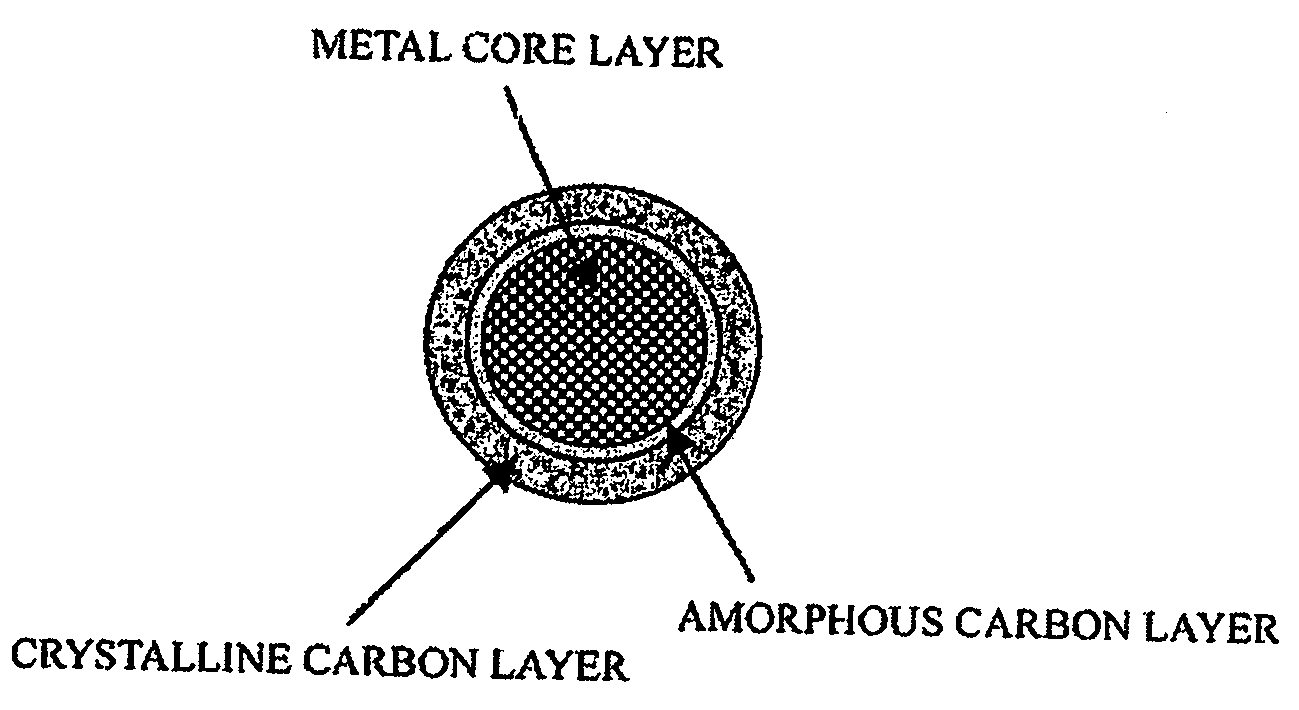
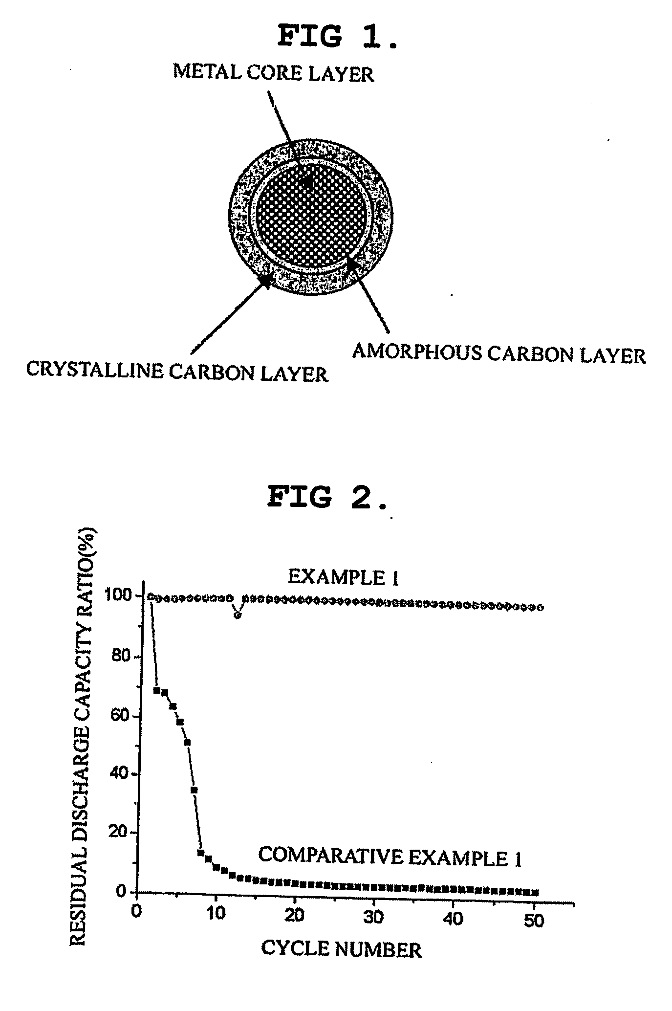
[0048] Natural graphite was mixed with Si in a ratio of 50 wt %:50 wt %. Then, mechanical alloying of the mixture was performed by using a Mechano Fusion device available from Hosokawa Micron Company under a rotation speed of 600 rpm for 30 minutes to obtain an anode material. As shown in FIG. 6, the resultant anode material was composed of a Si metal layer, an amorphous carbon layer and a crystalline carbon layer.

[0049] In order to evaluate the anode material, the anode material powder was mixed with 10 wt % of PVDF as a binder, 10 wt % of acetylene black as a conducting agent and NMP as a solvent to form homogeneous slurry. The slurry was coated on a copper foil, dried, rolled and then punched into a desired size to obtain an anode. A coin type cell was formed by using the anode, a lithium metal electrode as a counter electrode and an electrolyte containing 1 mole of LiPF6 dissolved in EC and EMC.

example 2

[0050] Example 1 was repeated to obtain an anode material and a coin type cell, except that Si was substituted with an alloy having the composition of Si 62 wt %+Co 38% and obtained by a gas atomization method.


PUM


Abstract

Disclosed is an anode material comprising a metal core layer capable of repetitive lithium intercalation / deintercalation; an amorphous carbon layer coated on the surface of the metal core layer, and a crystalline carbon layer coated on the amorphous carbon layer. The anode material not only maintains a high charge / discharge capacity, which is an advantage of a metal-based anode material, but also inhibits changes in the volume of a metal core layer caused by repetitive lithium intercalation / deintercalation in virtue of an amorphous carbon layer and a crystalline carbon layer, thereby improving the cycle life characteristics of cells.

Description

TECHNICAL FIELD [0001] The present invention relates to an anode material for a lithium secondary cell and a lithium secondary cell using the same. BACKGROUND ART [0002] Currently, carbonaceous materials are used as anode materials for lithium secondary cells. However, it is necessary to use an anode material with a higher capacity in order to further improve the capacity of a lithium secondary cell. [0003] For the purpose of satisfying such demands, metals capable of forming alloys electrochemically with lithium, for example Si, Al, etc., which have a higher charge / discharge capacity, may be considered for use as anode materials. However, such metal-based anode materials undergo extreme changes in volume, as lithium intercalation / deintercalation progresses, and thus the active materials are finely divided and the lithium cells have poor cycle life characteristics. [0004] Japanese Patent Application Laid-Open No. 2001-297757 discloses an anode material essentially comprising an α-ph...

Claims


Application Information

Patent Timeline
IPC IPC(8): H01M4/62H01M4/58H01M4/04B05D5/12H01M4/134H01M4/00H01M4/1395H01M4/36H01M4/38H01M4/40H01M10/02H01M10/052
CPCH01M4/0402Y02E60/122H01M4/13H01M4/133H01M4/134H01M4/139H01M4/366H01M4/38H01M4/40H01M4/405H01M4/587H01M4/625H01M10/052H01M10/0525H01M2004/027H01M4/0416H01M4/386H01M4/387Y02E60/10H01M4/36H01M4/04
Inventor KIM, YOU MINLEE, KI YOUNGLEE, SEO JAEROH, SUK MYUNGKWON, OU JUNG
Owner LG ENERGY SOLUTION LTD
Learn More