Hydrogen Gas Generation system

a hydrogen gas and generation system technology, applied in the direction of combustible gas production, fluid pressure control, instruments, etc., can solve the problem that the design does not provide orientation independent operation, and achieve the effect of reducing the overall volume and preventing heat exchang

Inactive Publication Date: 2006-10-26
SILICON VALLEY BANK
View PDF14 Cites 16 Cited by
  • Summary
  • Abstract
  • Description
  • Claims
  • Application Information

AI Technical Summary

Benefits of technology

[0009] In U.S. patent application Ser. No. 09 / 902,900 entitled “Differential Pressure Driven Borohydride Based Generator, filed Jul. 11, 2001, and owned by the present assignee, the content of which is hereby incorporated herein by reference into the present application its entirety, a single volume exchanging tank is incorporated into a hydrogen generator as part of a fuel reservoir to feed the active fuel chamber. As fuel is consumed from the fuel area and borate solution is returned to the borate solution area, the movable partition slides such that space that was originally occupied by fuel becomes occupied by borate solution. This has the obvious advantage of reducing the overall volume needed to store both fuel and borate solution. As the hydrolysis reaction of chemical hydride is exothermic, the borate solution is usually discharged at a higher temperature than the fuel solution; the movable partition can be designed as a heat insulator to prevent heat exchange between the two regions. This design does not, however, provide for orientation independent operation.
[0010] The metal hydride fuel component of the disclosed system is a complex metal hydride that is water soluble and stable in aqueous solution. Examples of suitable metal hydrides are those having the general formula MBH4 where M is an alkali or alkaline earth metal selected from Group I or Group 2 of the periodic table, such as lithium, sodium, potassium, calcium and magnesium. Examples of such compounds include, without limitation, NaBH4, LiBH4, KBH4, Ca(BH4)2 and Mg(BH4)2. These metal hydrides may be utilized in mixtures, but are preferable utilized individually. Preferred for such systems in accordance with the present invention is sodium borohydride (NaBH4). Sodium borohydride can be dissolved in alkaline water solutions with virtually no reaction and the aqueous SBH fuel solutions are non-volatile and will not burn. This imparts handling and transport ease both in the bulk sense and within the hydrogen generator itself.

Problems solved by technology

This design does not, however, provide for orientation independent operation.

Method used


Image

  • Hydrogen Gas Generation system
  • Hydrogen Gas Generation system
  • Hydrogen Gas Generation system

Examples


Embodiment Construction

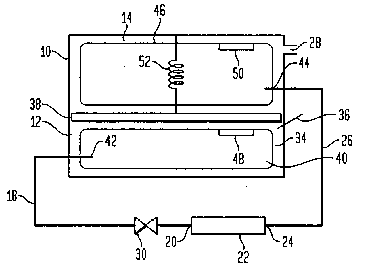
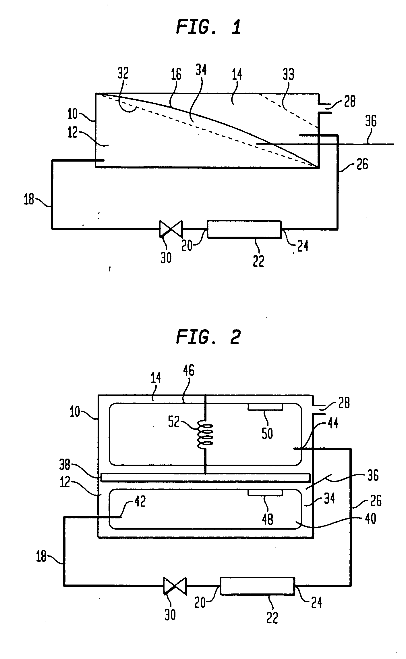
[0019] In an embodiment of the invention shown in FIG. 1, the hydrogen gas generation system includes a housing 10 which can be constructed of a relatively strong material as is necessary to carry out the purposes of the present invention. Within the housing 10 there is formed a fuel storage chamber 12 and a hydrogen separation chamber 14 separated by a flexible partition 16. The fuel storage chamber 12 normally contains the fuel solution that is reactive to produce hydrogen gas and is a hydride solution and can be a stabilized metal hydride solution, such as sodium borohydride.

[0020] The flexible partition 16 can be a ribbon spring or a preformed piece of flexible plastic or similar material that has an intrinsic tension and can maintain an applied pressure on the fuel solution within the fuel storage chamber 12. When the fuel storage chamber 12 is full of the fuel solution, the flexible partition 16 is expanded into a high energy “extended” state. As the flexible partition 16 con...


PUM

PropertyMeasurementUnit
hydrogen pressureaaaaaaaaaa
permeableaaaaaaaaaa

Abstract

A system for generating hydrogen gas utilizes a volume exchange housing for the storage of a fuel material that reacts to generate hydrogen gas and a hydrogen separation chamber. The system includes a gas permeable membrane or membranes that allow hydrogen gas to pass through the membrane while preventing aqueous solutions from passing therethrough. The system is orientation independent. A throttle valve is also used to self regulate the reaction generating the hydrogen gas.

Description

FIELD OF THE INVENTION [0001] The invention relates to a system for generating hydrogen gas using a catalyst from a fuel such as borohydride. More particularly, the invention relates to a system for hydrogen generation having a volume-exchange system for the storage of fuel solution and discharged product and a hydrogen filtration system. BACKGROUND OF THE INVENTION [0002] Hydrogen is a “clean fuel” because it can be reacted with oxygen in hydrogen-consuming devices, such as a fuel cell or combustion engine, to produce energy and water. Virtually no other reaction byproducts are produced in the exhaust. As a result, the use of hydrogen as a fuel effectively solves many environmental problems associated with the use of petroleum based fuels. Safe and efficient storage of hydrogen gas is, therefore, essential for many applications that can use hydrogen. In particular, minimizing volume, weight and complexity of the hydrogen storage systems are important factors in mobile applications....

Claims


Application Information

Patent Timeline
Patent Type & Authority Applications(United States)
IPC IPC(8): B01J8/00C01B3/06C01B3/50F17C11/00H01M8/06
CPCC01B3/065C01B3/501C01B2203/0405C01B2203/0465C01B2203/0495Y02E60/362H01M8/04208H01M8/04216H01M8/065H01M8/0662Y02E60/321F17C11/005Y02E60/36Y02E60/32Y02E60/50C01B3/26C01B3/38C01B3/06B01J7/02
Inventor STRIZKI, MICHAELMOHRING, RICHARD M.
Owner SILICON VALLEY BANK
Why Eureka
Try Eureka