
Quartz glass crucible for pulling up silicon single crystal and method for manufacture thereof

a technology of silicon single crystal and glass crucible, which is applied in the direction of polycrystalline material growth, manufacturing tools, and under a protective fluid, can solve the problems of deformation or peeling of the transparent inner layer, distortion at the boundary between the two layers, and inconvenient yield, so as to suppress the occurrence of glass dissolving surface and improve the yield of pulling up a single crystal.

Active Publication Date: 2006-10-26
HERAEUS QUARZGLAS +1
View PDF10 Cites 37 Cited by
  • Summary
  • Abstract
  • Description
  • Claims
  • Application Information

AI Technical Summary

Benefits of technology

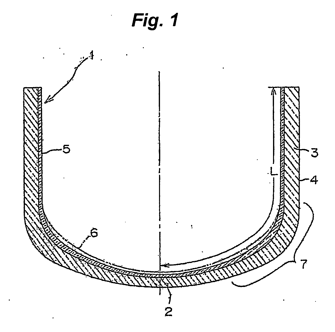
[0012] The first quartz glass crucible of the present invention is, as described above, a quartz glass crucible in which a transparent Layer made of natural quartz glass is provided on the inside of an opaque outer layer made of natural quartz glass, a transparent layer made of a synthetic quartz glass is formed on the inside of the crucible in the range from at least 0.15 to 0.55 L in terms of a distance (L) from the center of the bottom of the transparent layer to the upper end face along the inner surface of the crucible, distortion at the boundary between the transparent layer made of a synthetic quartz glass and the opaque outer layer made of natural quartz glass is alleviated, and deformation or peel-off of the transparent layer does not occur. The thickness of the above-mentioned transparent layer made of natural quartz glass may be in the range from 0.4 to 5.0 mm, preferably from 0.7 to 4.0 mm. When the thickness of the transparent layer made of natural quartz glass is in the above-mentioned range, the function as a buffering portion is optimized. In addition, the transparent layer made of a synthetic quartz glass is not formed in the range from 0.6 to 1.0 L in terms of a distance (L) from the center of the bottom of the inner surface of the crucible to the upper end face along the inner surface of the crucible, or even if it is formed, the thickness thereof is set to 0.2 mm or less. By forming a transparent layer made of natural quartz glass, not of a synthetic quartz glass, on the inner surface in the above-mentioned range, vibration of a silicon melt can be suppressed. Further, even if a transparent layer made of a synthetic quartz glass is formed, if the thickness thereof is 0.2 mm or less, the transparent layer made of a synthetic quartz glass is melted and damaged by the time of melting a polysilicon (meltdown) and starting the pulling up, and the natural quartz glass layer is exposed, whereby vibration of a silicon melt can be suppressed. In this case, compared with a case where a transparent layer made of a synthetic quartz glass is not formed, the amount of natural quartz glass melted in a silicon melt during the melt down is small, therefore, impurities melted in the silicon melt can be reduced.
[0013] Incidentally, the yield in the pulling up of a silicon single crystal varies depending on dislocation generation in a single crystal, however, it is mostly generated in the latter half of the pulling up step, namely it is caused by surface roughness on the inner surface or peel-off of the inner layer which occurs in the range from the bent portion to the vicinity of the bottom of a quartz glass crucible (in the range from at least 0.15 to 0.55 L in terms of a distance L from the center of the bottom of the inner surface of the crucible to the upper end face along the inner surface thereof) which is contacted with a silicon melt for a long time and to which a high heat load by a heater is applied. Therefore, by forming the inner surface in the above-mentioned range with a transparent layer made of a synthetic quartz glass, surface roughness or peel-off of the inner layer can be significantly reduced. Further, the used amount of a synthetic quartz powder can be reduced, and the cost for producing a quartz glass crucible can be reduced. The thickness of the above-mentioned transparent layer made of a synthetic quartz glass may be in the range from 0.2 to 1.5 mm. If the thickness is less than 0.2 mm, the effect on suppressing surface roughness or peel-off of the inner layer is small, and even if a layer with a thickness of more than 1.5 mm is formed, the effect on suppressing surface roughness or peel-off of the inner surface does not change, but the cost for producing a quartz glass crucible is increased instead, therefore it is not preferred.
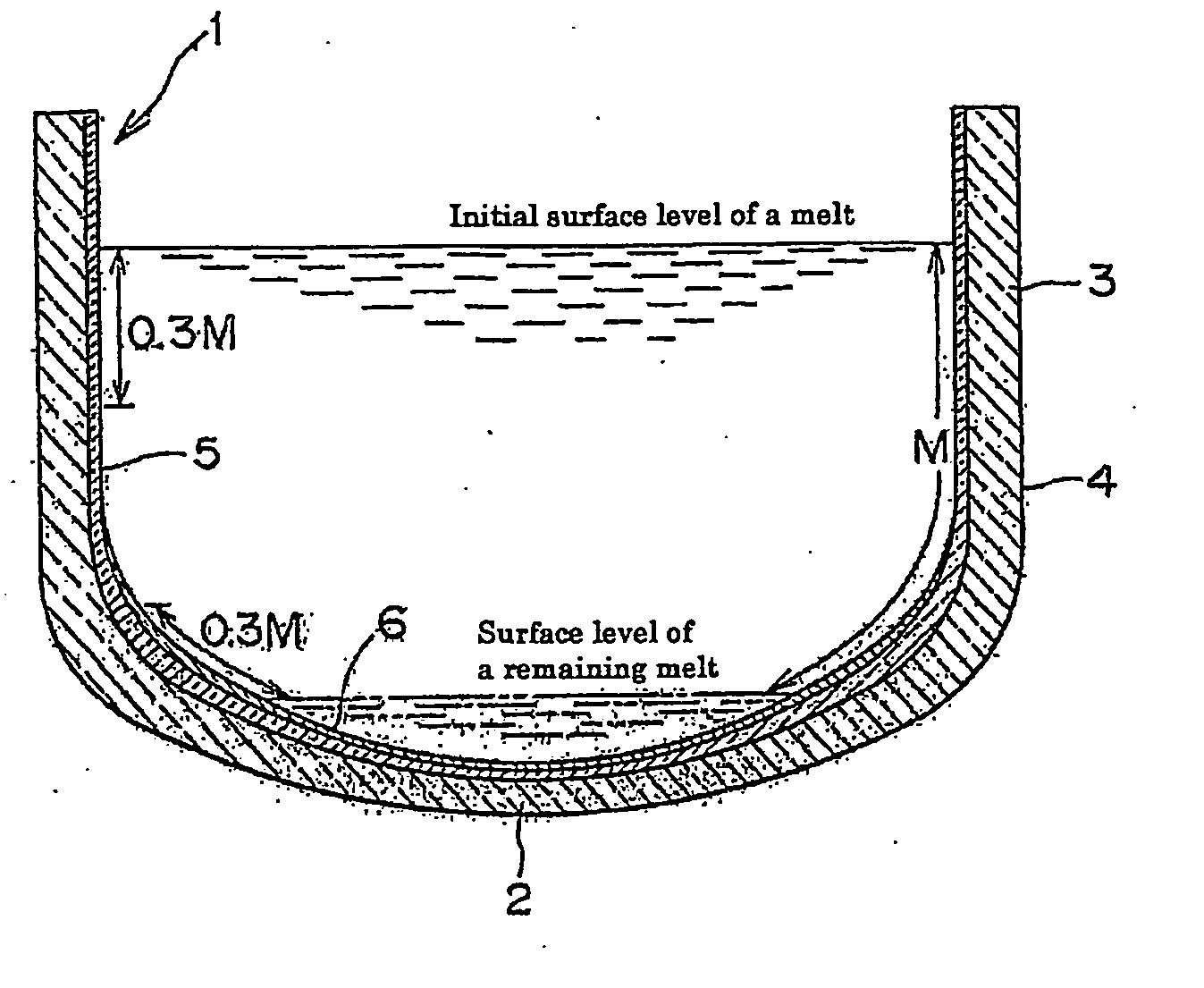
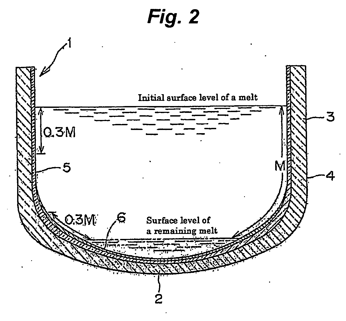
[0018] On the other hand, dislocations in a silicon single crystal are mostly generated in the range up to 0.3 M above the surface level of the remaining melt, however, this range is contacted with the silicon melt for a long time, therefore, a brown ring grows there and a glass dissolving surface as shown in FIG. 4(c) is liable to occur. Accordingly, by decreasing the number of brown rings in this range, the occurrence of the glass dissolving surface can be suppressed, and the yield in the pulling up of a single crystal can be improved. In addition, even if the number of brown rings in this range is decreased, there is no effect on vibration of the silicon melt.

Problems solved by technology

Once this glass dissolving surface emerges, dislocations are liable to be generated in a silicon single crystal, which entails inconvenience in the yield in the pulling up of a single crystal.
However, in the case where a transparent inner layer is composed of a synthetic quartz glass and an outer layer is composed of an opaque quartz glass made of natural quartz glass, the physical properties vary widely between the transparent inner layer and the outer layer such as the difference between the fact that one is transparent and the other is opaque and the difference between the fact that one is made of a synthetic substance and the other is made of a natural one, therefore distortion is generated at the boundary between both layers.
In particular, there was a problem of deformation or peel-off of the transparent inner layer at a bent portion of a crucible to which a high heat load by a heater was applied and which was contacted with a silicon melt for a long time in some cases.
In addition, a crucible comprising a transparent inner layer made of a synthetic quartz glass had a drawback in that when a polysilicon was melted, the surface of the melt was liable to vibrate compared with a crucible comprising a transparent inner layer made of natural quartz glass.
This vibration was frequently observed particularly at the time from seeding to shoulder formation and in the step of pulling up a front half portion of a single crystal body at an initial stage; therefore, it took a long time to perform seeding, a crystal was disordered and melted again, that is, so-called melt back occurred, and soon, whereby the productivity was decreased in some cases.
Therefore, as disclosed in JP-A-2001-348294, a crucible with a multilayer structure having an opaque intermediate layer made of a synthetic quartz glass between a transparent inner layer made of a synthetic quartz glass and an opaque bulk layer made of natural quartz glass has been proposed, however, there was a drawback in that since a large amount of expensive synthetic quartz powder was used for the crucible with a multilayer structure, the price of the quartz glass crucible was high.
On the other hand, when the number of brown rings occurring on the inner surface of a crucible in the CZ method is reduced, the surface of a silicon melt is liable to vibrate at the time of pulling up a crystal; therefore there is a problem of deterioration of workability.

Method used


Image

  • Quartz glass crucible for pulling up silicon single crystal and method for manufacture thereof
  • Quartz glass crucible for pulling up silicon single crystal and method for manufacture thereof
  • Quartz glass crucible for pulling up silicon single crystal and method for manufacture thereof

Examples


example 1

[0024] By using an apparatus shown in FIG. 3, natural silica powder of high purity subjected to a purification treatment was fed into a rotatable mold 8, and a crucible-like molded article 9 was formed by utilizing centrifugal force. Then, an arc electrode 14 was inserted in the article, and the opening portion was covered with a plate-like lid 11. Then, the inside of the inner cavity was made a high temperature gas atmosphere by the arc electrode 14, melted and vitrified, and then cooled, whereby an opaque outer layer 4 with a thickness of 8 to 10 mm was produced. Subsequently, the inner cavity of the opaque outer layer 4 was made a high temperature atmosphere 16 by the arc electrode 14 while rotating the mold 8, and then natural silica powder was fed at 100 g / min from a silica powder feeding nozzle 15, whereby a transparent layer 5 with a thickness of 0.9 to 2 mm made of natural quartz glass was fused and integrated to the inner surface of the opaque outer layer 4. Subsequently, a...

examples 2 to 5

[0025] In Example 1, the transparent layer 5 made of natural quartz glass and the transparent layer 6 made of a synthetic quartz glass, which form the inner surface of a quartz glass crucible, were fused and integrated so as to have a thickness shown in Table 1, respectively, whereby a 24-inch quartz glass crucible was produced. The average OH group concentration in each layer of the produced quartz glass crucible was as shown in Table 1. By using this quartz glass crucible, pulling up of a silicon single crystal was carried out in the same manner as in Example 1. The results are shown in Table 1.

TABLE 1Example 2Example 3Example 4Example 5Transparent layerThickness0 to 0.55 L: 1 to 3 mm;0 to 0.1 L: 0 mm;0 to 0.55 L: 0.3 to 0.8 mm;0 to 0.55 L:made of synthetic0.55 to 0.6 L: 0.2 to 1 mm;0.1 to 0.15 L: 0 to 0.3 mm:0.55 to 0.6 L: 0 to 0.3 mm;0.3 to 0.8 mm;quartz glass0.6 to 1 L: 0.1 to 0.2 mm0.15 to 0.55 L: 0.3 to 1.2 mm;0.6 to 1 L: 0 mm0.55 to 0.6 L:0.55 to 0.6 L: 0.2 to 0.4 mm;0 to ...

example 6

[0027] By using an apparatus shown in FIG. 3, natural silica powder of high purity subjected to a purification treatment was fed into a rotatable mold 8, and a quartz glass crucible-like molded article 9 was formed by utilizing centrifugal force. Then, an arc electrode 14 was inserted in the article, and the opening portion was covered with a plate-like lid 11. Then, the inside of the inner cavity was made a high temperature gas atmosphere by the arc electrode 14, melted and vitrified, whereby an opaque quartz glass outer layer 4 was produced. Subsequently, natural silica powder was fed at 100 g / min from a silica powder feeding device 10, whereby a transparent layer 5 made of natural quartz glass was fused and integrated to the inner surface of the opaque quartz glass outer layer 4. Then, a synthetic silica powder was fed at 100 g / min from a silica powder feeding device 15, and after the use in the pulling up of a silicon single crystal, a transparent layer 6 made of a synthetic qua...


PUM

PropertyMeasurementUnit
Fractionaaaaaaaaaa
Fractionaaaaaaaaaa
Fractionaaaaaaaaaa

Abstract

A quartz glass crucible which has a non-transparent outer layer formed through melting a natural silica powder and a transparent layer formed in the inside of the outer layer, wherein the transparent layer comprises a natural quartz layer having a thickness of 0.4 to 5.0 mm transparent layer comprising a synthetic quarts glass is formed thereon in the inside of the crucible in the range of 0.15 to 0.55 L relative to L, which is the distance from the center of the bottom of the inner surface of the quartz glass crucible to the upper end thereof along the inner surface thereof. The quartz glass crucible can be suitably used for suppressing the occurrence of vibration and reducing the generation of roughened face in the surface of a crucible, and thus for pulling up a silicon single crystal with enhanced stability.

Description

TECHNICAL FIELD [0001] The present invention relates to a quartz glass crucible for pulling up a silicon single crystal and a process for producing the same. BACKGROUND ART [0002] A method which is called Czochralski method (CZ method) has heretofore widely been adopted in production of silicon single crystals. This CZ method is a method in which polycrystal silicon is melted in a crucible made of a quartz glass, a seed crystal of a silicon single crystal is dipped into this silicon melt and the seed crystal is gradually pulled up while rotating the crucible, to grow a silicon single crystal by employing a seed crystal as a nucleus. It is necessary that the single crystal produced by the above-mentioned CZ method is of high purity and is also enabled to produce a silicon wafer in high yield. As for a quartz glass crucible to be used in the production, a quartz glass crucible having a two layer structure comprising a transparent inner layer that does not contain bubbles and an opaque...

Claims


Application Information

Patent Timeline
IPC IPC(8): C30B15/00C30B21/06C30B27/02C30B28/10C30B30/04C30B11/00C03B19/09C30B15/10
CPCC03B19/095C30B15/10Y10T117/1052Y10T117/1032Y10T117/10C30B29/06
Inventor OHAMA, YASUO
Owner HERAEUS QUARZGLAS
Learn More