Method of dyeing or reforming injection, blow or compression molding
- Summary
- Abstract
- Description
- Claims
- Application Information
AI Technical Summary
Benefits of technology
Problems solved by technology
Method used
Image
Examples
example 1
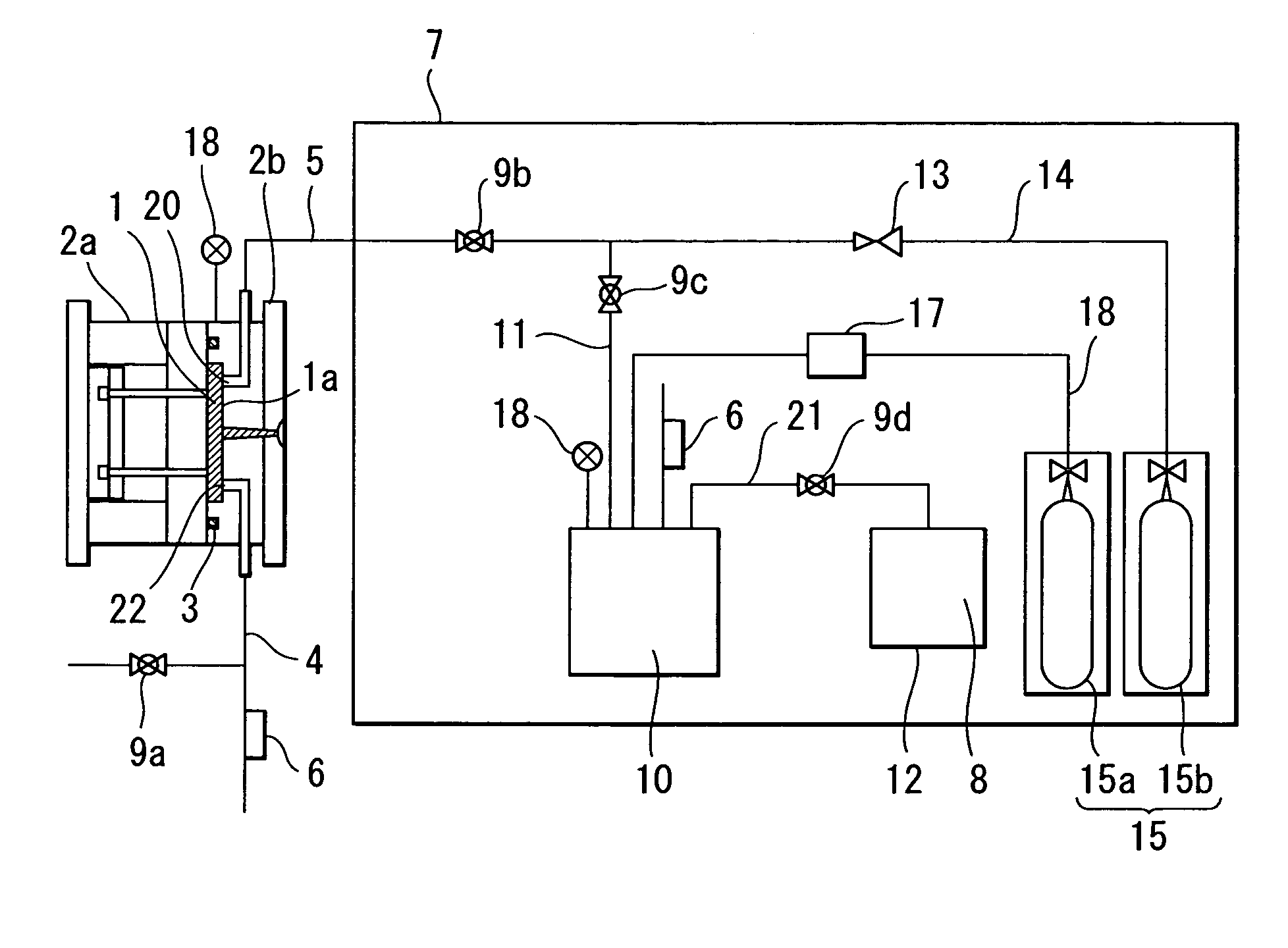
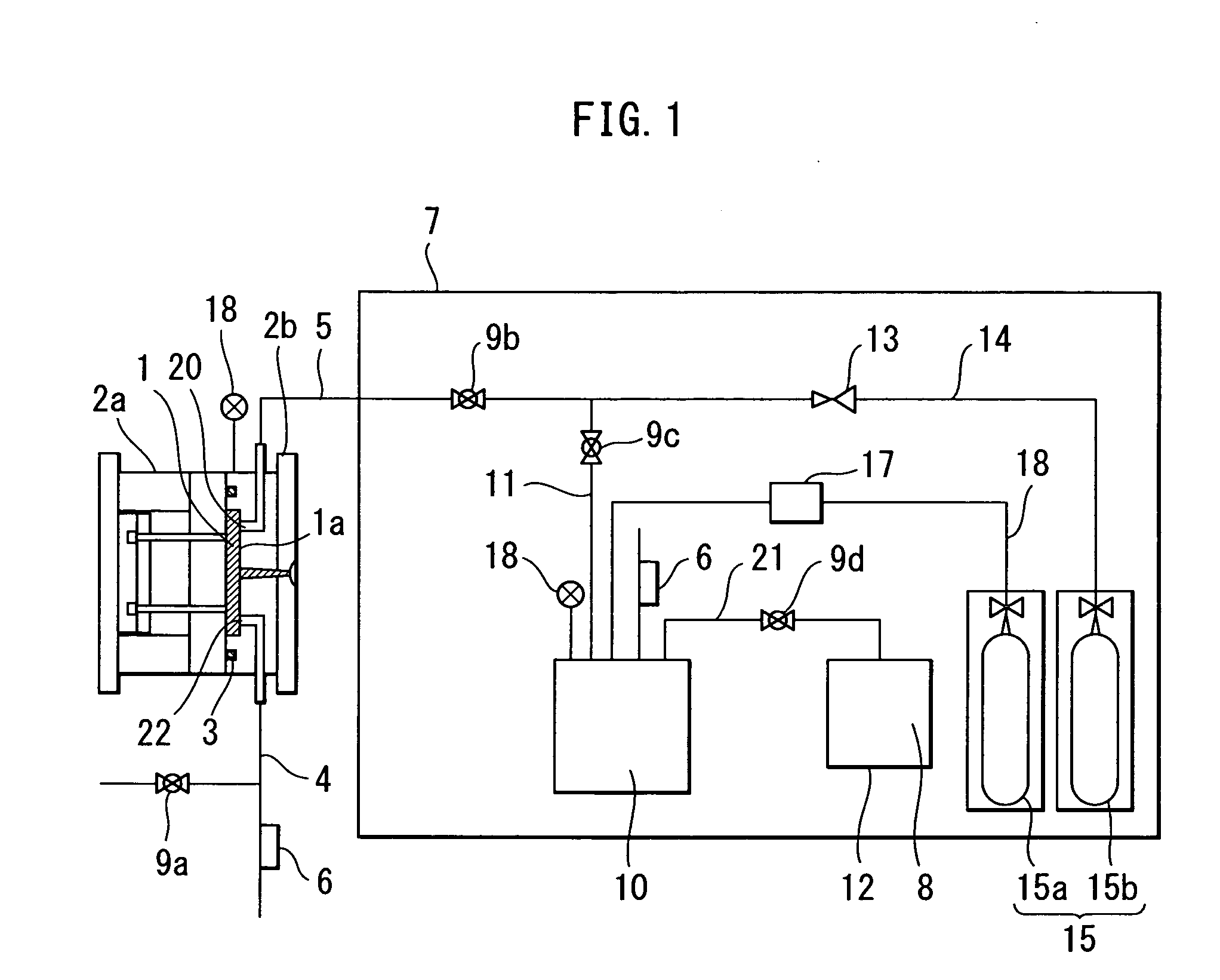
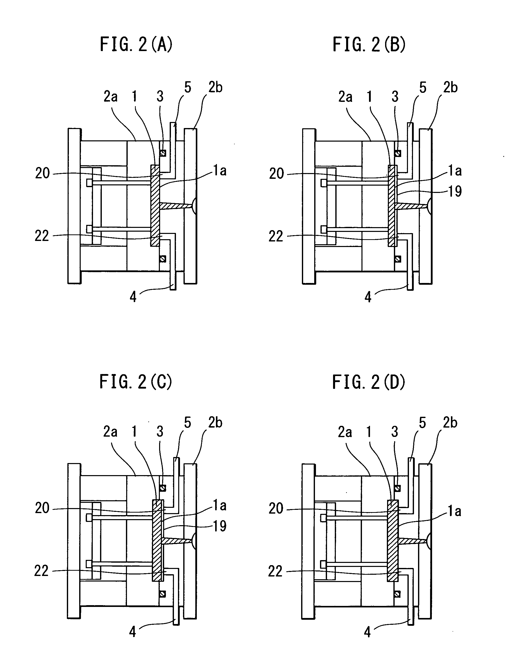
[0053] An embodiment of the invention according to claim 1 is described below with reference to FIG. 1 and FIG. 2.
[0054]FIG. 1 shows a die and an injector employed for carrying out the present invention. The reference numeral 1 indicates a cavity formed when a die 2b in the fixed side and a die 2a in the movable side are tightened to each other; the reference numeral 3 indicates a O-ring for preserving a gas pressure in the cavity and preventing leakage of gas to outside of the cavity; the reference numerals 9a, 9b, 9c, 9d indicates electromagnetic switching control value for controlling; reference numeral 18 indicates a pressure gauge; and the reference numeral 6 indicates a back pressure valve for exhausting a gas to the outside only when a gas pressure in the cavity or in each vessel is not less than a prespecified pressure level. Further the reference numeral 4 indicates a gas exhaust line connected the back pressure value to a gas exhaust port 22 for exhausting a gas inside th...
example 2
[0062] Molding was performed by changing the conditions for gas injection employed in Example 1 such as a temperature of a mixture of carbon dioxide and an organic azo disperse dye, time for injection, and an injection pressure. In Example 2, the gas temperature was set to 50, 60, and 70° C, the gas injection time was set to 0.5, 1.0 and 2.0 seconds, and the injection pressure was set to 5, 10, and 15 MPa. The molded products obtained as described above were substantially influenced by a temperature of the mixed gas, injection pressure, and injection time, and with any of the parameters described above, the higher temperature, highest pressure, and longest injection time provided molded products excellently colored and reformed. A cross section of each product was observed with a CCD camera zoom lens (produced by K.K Keyence; VH-Z150), and degrees of dyeing and reformation were assessed. A result is shown in Table 2.
example 3
[0065] FIG., 3A to FIG. 3D correspond to the invention according to claim 4, and polycarbonate (produced by Mitsubishi Engineering Plastic K.K.: H3000) as resin. The molded product obtained in this step has the size of 32.00 mm (length), 32.0 mm (width), and 2.0 mm (thickness). Further, this molded product was filled in the die cavity 1 (made from material S45C, bushing type) with pressurized hot water under the conditions of injection pressure of 56 MPa, filing time of 0.5 second, and melted resin temperature of 280° C. In this molding method, immediately after the melted resin was filled, kept in the pressurized state, and cooled, the die 2a in the movable side was retarded to release the die tightening pressure, and a clearance of about 0.1 mm, or in the range from 0.1 mm to 1.0 mm was forcefully formed between the skin layer in the visible side and the cavity face 1a (A), and any of the mixture gases employed in Example 1 with the pressure set to 15.0 MPa was kept under the pres...
PUM
| Property | Measurement | Unit |
|---|---|---|
| Depth | aaaaa | aaaaa |
| Distance | aaaaa | aaaaa |
| Distance | aaaaa | aaaaa |
Abstract
Description
Claims
Application Information
 - R&D
- Intellectual Property
- Life Sciences
- Materials
- Tech Scout
- Unparalleled Data Quality
- Higher Quality Content
- 60% Fewer Hallucinations
Browse by: Latest US Patents, China's latest patents, Technical Efficacy Thesaurus, Application Domain, Technology Topic, Popular Technical Reports.
© 2025 PatSnap. All rights reserved.Legal|Privacy policy|Modern Slavery Act Transparency Statement|Sitemap|About US| Contact US: help@patsnap.com


