Method for analyzing overlay errors

a technology of overlay error and analysis method, which is applied in the field of photolithography processes, can solve the problems of isotropic magnification error, fewer works have addressed overlay error models of advanced scanners, and the overlay error models suitable for lithography processes using steppers mostly do not fit the scanners, so as to improve the accuracy of overlay error analysis

Inactive Publication Date: 2006-10-26
MACRONIX INT CO LTD
View PDF10 Cites 25 Cited by
  • Summary
  • Abstract
  • Description
  • Claims
  • Application Information

AI Technical Summary

Benefits of technology

[0010] This invention also provides a new sampling strategy, especially a new interfield sampling pattern, which is suitably used together with the new overlay error model to further improve the performance of the overlay analyzing method of this invention.
[0013] On the other hand, the interfield sampling pattern of this invention includes at least four fields that have four different X-coordinates and four different Y-coordinates, wherein each field is apart from the center of the wafer by at least 50% of the radius of the wafer, and an angle between any two fields with respect to the center of the wafer is at least 30°. The interfield sampling pattern may further include one field around the center of the wafer, so as to further improve the accuracy of overlay error analyses.
[0014] In more preferable embodiments of this invention, the above intrafield sampling pattern of “four corners plus center” type and the new interfield sampling pattern of this invention are used in combination to further improve the accuracy of overlay error analyses. The sampling strategy is also a part of this invention.

Problems solved by technology

However, most of the existing studies are focused on stepper lithography, while fewer works have addressed overlay error models of the advanced scanner lithography and corresponding sampling strategies.
The overlay error models suitable for lithography processes using steppers mostly do not fit for those using scanners.
Intrafield translation error is caused by translation of the reticle, and isotropic magnification error occurs when the lens moves closer to the reticle or to the wafer.
Interfield translation error is caused by translation of the wafer.
Scale error will occur if an absolute movement is given to the stage but results in the stage moving by another amount.
Orthogonality error is caused by that the X-Y coordinate system is not parallel to the wafer stage.
However, none of the conventional overlay models fits well enough for lithography processes using scanners.
Therefore, the overlay errors occurring in a lithography process using a scanner cannot be analyzed correctly and compensated effectively, so that the accuracy of pattern transfer is difficult to improve.

Method used


Image

  • Method for analyzing overlay errors
  • Method for analyzing overlay errors
  • Method for analyzing overlay errors

Examples


examples

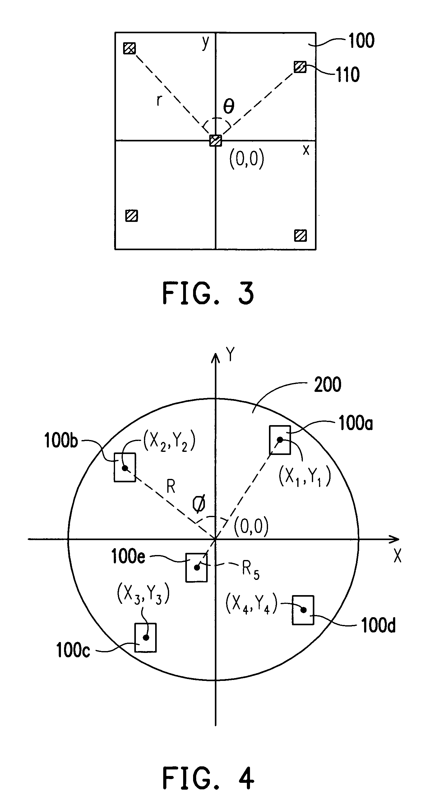
[0033] The preferable intrafield sampling pattern in FIG. 3 and the interfield sampling pattern of this invention illustrated in FIG. 4 are evaluated in the following examples. The preferable intrafield sampling pattern in combination with a fixed conventional interfield sampling pattern is evaluated first, and then the interfield sampling pattern of this invention in combination with a fixed intrafield sampling pattern is evaluated. Finally, combinations of different intrafield and interfield sampling patterns including the interfield sampling patterns of this invention and the preferable intrafield sampling patterns, like in FIG. 9, are compared.

[0034]FIG. 5 illustrates eight intrafield sampling patterns for evaluation, wherein the patterns (A), (B), (C) and (D) of “four corners plus center” type are examples of this invention. FIG. 6 shows the fixed interfield sampling pattern applied in the evaluation. The interfield sampling pattern of FIG. 6 is not an interfield sampling patt...


PUM


Abstract

A method for analyzing overlay errors in lithography is described. Interfield sampling and intrafield sampling are first conducted to sample multiple positions on each of the wafers, and then the overlay error value at each of the positions is measured. An overlay error model including coefficients of intrafield and interfield overlay errors of different types is used to fit the measured overlay error values with respect to the sampled positions. In the overlay error model, the intrafield overlay errors include intrafield translation, isotropic magnification, reticle rotation, asymmetric magnification and asymmetric rotation, and the interfield overlay errors include interfield translation, scale error, wafer rotation and orthogonality error.

Description

BACKGROUND OF THE INVENTION [0001] 1. Field of the Invention [0002] The present invention relates to photolithography processes. More particularly, the present invention relates to a method for analyzing overlay errors that occur in a lithography process. The method utilizes a new overlay error model to improve the accuracy of overlay error analyses. [0003] 2. Description of the Related Art [0004] With decreasing feature sizes and shrinking linewidths of integrated circuits, lithography has become critical for semiconductor manufacture. As the tolerance of linewidth error is increasingly small, lithography machines have been upgraded from step-and-repeat systems (steppers) to advanced step-and-scan systems (scanners). To enhance the resolution and alignment accuracy in lithography, it is necessary to control the overlay errors of lithography to within a tolerance. [0005] Overlay errors are the displacements of present layers relative to the preceding layers, and can be controlled by...

Claims


Application Information

Patent Timeline
Patent Type & Authority Applications(United States)
IPC IPC(8): G01B11/00
CPCG03F7/70633G03F7/705
Inventor LIN, SHUN-LICHIEN, CHEN-FUHSU, CHIA-YUWU, I-PIEN
Owner MACRONIX INT CO LTD
Why Eureka
Try Eureka