Optical scanning system and image forming apparatus using the same

a scanning system and image forming technology, applied in the direction of printing, inking apparatus, instruments, etc., can solve the problems of changing the shape of the imaging lens along the main, increasing the overall size of the optial scanning system, and so as to achieve higher quality images, reduce and achieve the effect of reducing the overall size of the optial scanning system

Inactive Publication Date: 2006-10-26
CANON KK
View PDF4 Cites 6 Cited by
  • Summary
  • Abstract
  • Description
  • Claims
  • Application Information

AI Technical Summary

Benefits of technology

[0028] The present invention has been made to solve or reduce at least one of the inconveniences described hereinbefore, and it is accordingly an object of the present invention to realize that, even when the thickness of an imaging lens is made small to meet low-cost plastic molding, the optical magnification upon a scan surface in the sub-scan direction is maintained constant.
[0029] It is another object of the present invention to provide a scanning lens which is easy to manufacture and by which deterioration of the light spot shape as well as degradation of performance due to a relative positional deviation of the lens surfaces are prevented or reduced.
[0030] It is a yet further object of the present invention to provide an optical scanning system by which the overall size of the optical scanning system can be made small, by which the light spot diameter in the sub-scan direction can be made uniform inside an effective scan region, by which both of single-beam scan and multiple-beam scan can be met, and by which higher-quality images can be produced at higher speed.
[0044] Briefly, in accordance with the present invention, the shape of an imaging optical element or the like that constitutes an imaging optical system is designed in the best way to reduce the overall size of the optial scaning system and also to make uniform the light spot diameter in the sub-scan direction, throughout the effective scan region.
[0045] Furthermore, in accordance with the present invention, an optical scanning system and an image forming apparatus that can meet both of single-beam scan and multiple-beam scan and that can produce higher-quality images at higher speed are accomplished.

Problems solved by technology

Thus, there is a problem that increasing the speed is difficult to attain.
Furthermore, in the optical scanning system of Patent Document No. 1, although it can realize smallness in size that the scan width is 216 mm and the optical path length is not greater than 150 mm, high-speed scan is difficult to accomplish.
However, in the optical scanning system of Patent Document No. 3, the rate of change in the shape of the imaging lens along the main-scan sectional plane is too large so that, through a relative positional deviation of lens surfaces in the main-scan direction, a focus error is easily produced in the main-scan direction.
However, for a thin lens which is particularly preferable when an imaging lens is to be produced by plastic molding, the optical magnification on the scan surface in the sub-scan direction can not be maintained exactly constant.
Furthermore, there is an inconvenience that, due to a relative positional deviation of the lens surfaces in the main-scan direction, a focus error in the main-scan direction is easily produced.
Moreover, in order that the optical magnification on the scan surface in the sub-scan direction is made constant, the thickness of the imaging lens has to be enlarged which is very undesirable when the imaging lens produced in accordance with a plastic molding process.

Method used


Image

  • Optical scanning system and image forming apparatus using the same
  • Optical scanning system and image forming apparatus using the same
  • Optical scanning system and image forming apparatus using the same

Examples


embodiment 1

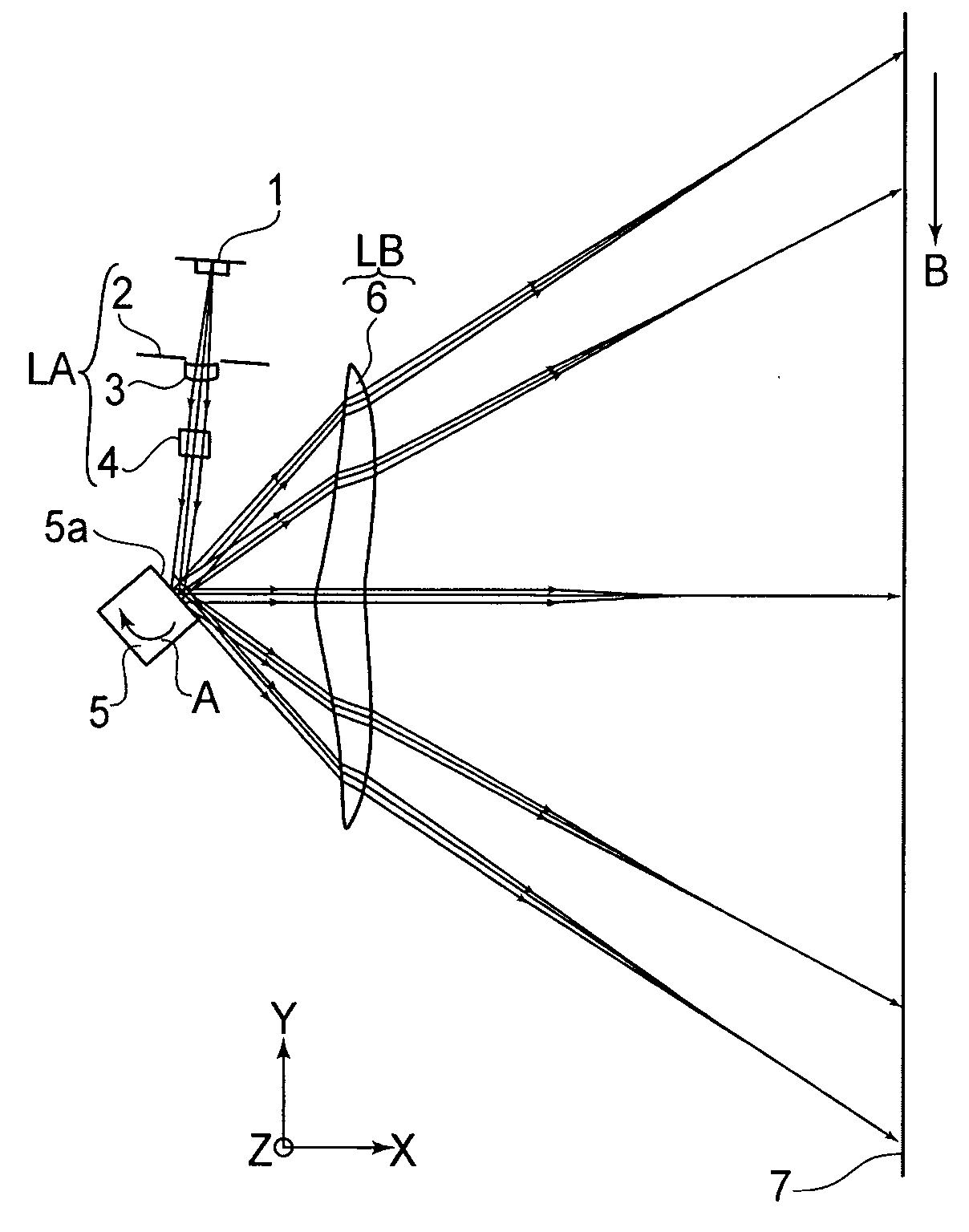
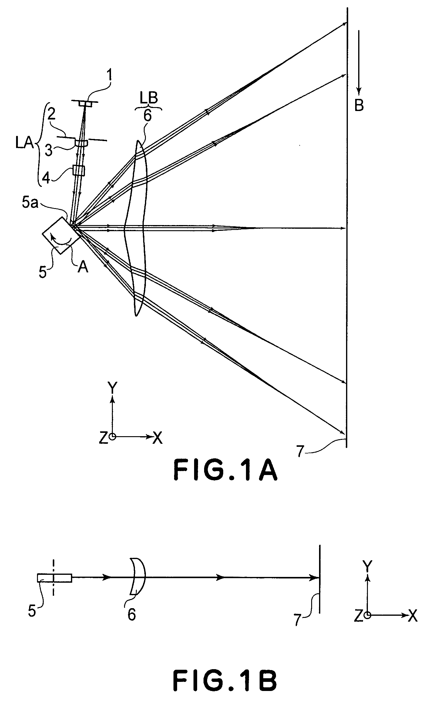
[0067]FIG. 1A is a sectional view (main-scan sectional view) in the main-scan direction of a main portion of an optical scanning system according to a first embodiment of the present invention. FIG. 1B is a sectional view (sub-scan sectional view) in the sub-scan direction of the main portion of the optical scanning system according to the first embodiment of the present invention.

[0068] Here, the term “main-scan direction” refers to the direction which is perpendicular to the rotational axis of a rotary polygonal mirror and to the optical axis of an imaging optical system, that is, the direction in which a light beam is reflectively deflected (deflectively scanned) by the rotary polygonal mirror.

[0069] The term “sub-scan direction” refers to the direction which is parallel to the rotational axis of the rotary polygonal mirror.

[0070] The term “main-scan sectional plane” refers to a plane that contains the main-scan direction and the optical axis of the imaging optical system.

[00...

embodiment 2

[0161] Next, an optical scanning system according to a second embodiment of the present invention will be described.

[0162] This embodiment differs from the first embodiment in that the light source means comprises a monolithic multiple-beam semiconductor laser having two light emission points. The remaining portion has a similar structure and optical function as of the first embodiment, and similar advantageous results are obtained therefrom.

[0163] Although in this embodiment a monolithic multiple-beam semiconductor laser having two light emission points is used, the present invention is applicable also where a monolithic multiple-beam semiconductor laser having three or more light emission points is used.

[0164] As seen in FIG. 7, the imaging magnification, with respect to the sub-scan sectional plane, of the optical scanning system according to the first embodiment is quite uniform inside the effective scan region. If the imaging magnification of the imaging optical system at th...


PUM


Abstract

Disclosed is an optical scanning system and an image forming apparatus using the same, which is designed to reduce the overall size of the system and to make uniform the light spot diameter in a sub-scan direction, inside an effective scan region, as well as to ensure high-speed production of high-quality images, wherein the optical scanning system includes a light source, a condensing optical system, a deflector and an imaging optical system having one or more optical elements, wherein, in at least one optical element of the optical elements, the curvature of the opposite surfaces thereof changes continuously, inside an effective region, from the optical axis toward the peripheral portion thereof so that the sign of the curvature is reversed at the middle, and wherein, when the curvature radius of the surface of that optical element facing the deflector side, at the optical axis and in the sub-scan sectional plane, is denoted by r10 while the least quantity of an absolute value of the curvature radius of the surface facing the scan surface side in an effective region of the portion where the sign of the curvature radius is reversed is denoted by |r2|min, the optical element satisfies a specific relation for them.

Description

FIELD OF THE INVENTION AND RELATED ART [0001] This invention relates to an optical scanning system and an image forming apparatus using the same. More particularly, the present invention concerns an optical scanning system which is suitably usable in a laser beam printer (LBP), a digital copying machine or a multifunction printer, for example, having an electrophotographic process. [0002] Conventionally, in optical scanning systems used in laser beam printers or digital copying machines, a light flux (light beam) optically modulated and emitted from light source means in accordance with an imagewise signal is periodically deflected by means of an optical deflector that may comprise a polygonal mirror, for example, and the deflected beam is focused into a light spot upon the surface of a photosensitive recoding medium by means of an imaging optical system which may comprise an f-θ lens. By scanning the recording medium surface with this light spot, imagewise recording is carried out....

Claims


Application Information

Patent Timeline
Patent Type & Authority Applications(United States)
IPC IPC(8): G02B26/08
CPCG02B26/125
Inventor ISHIBE, YOSHIHIRO
Owner CANON KK
Why Eureka
Try Eureka