

Optical device, light-condensing backlight system, and liquid crystal display
a backlight system and liquid crystal display technology, applied in the direction of polarising elements, instruments, chemistry apparatus and processes, etc., can solve the problems of increased number of parts, increased refractive index of condensation light with such elements, and increased light loss due to unnecessary scattering, etc., to improve front brightness and the degree of polarization, easy to design thin, and reduce coloration
- Summary
- Abstract
- Description
- Claims
- Application Information
AI Technical Summary
Benefits of technology
Problems solved by technology
Method used
Image

Examples
example 1
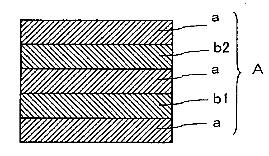
(Circular-Polarization-Type-Reflection Polarizer (a))
[0151] A broadband cholesteric liquid crystal layer having a reflection wavelength band from 400 to 800 nm was used as the circular-polarization-type-reflection polarizer (a). The retardation of the broadband cholesteric liquid crystal layer was measured to be 100 nm with respect to incident light with a wavelength of 550 nm inclined by 30°.
[0152] A spectroscopic ellipsometer (M-220 manufactured by JASCO Corporation) was used to measure the retardation of a cholesteric liquid crystal layer with a center wavelength of 370 nm. By the retardation, the wavelength dispersion of the refractive index was calculated using the Cauchy's formula for approximation: Retardation=a+bλ2+c / λ4 (see FIG. 7). All these values were automatically calculated by the equipment.
[0153] The result of cross-sectional TEM was used to determine variations in pitch length in the broadband cholesteric liquid crystal layer having a reflection wavelength band f...
example 2
(Circular-Polarization-Type-Reflection Polarizer (a))
[0169] The same broadband cholesteric liquid crystal layer as in Example 1 was used as the circular-polarization-type-reflection polarizer (a).
(Retardation Layer (b))
[0170] A photopolymerizable nematic liquid crystal monomer (LC242 manufactured by BASF Ltd.), a chiral agent (LC756 manufactured by BASF Ltd.), a photoinitiator (Irgacure 907 manufactured by Ciba Specialty Chemicals Inc.), and a solvent (toluene) were prepared and mixed to form a coating liquid for providing a center wavelength of 350 nm for selective reflection. The coating liquid was applied to a commercially available polyethylene terephthalate film with a wire bar so as to provide a post-drying coating thickness of 3 μm, and then the solvent was dried off. Thereafter, the liquid crystal monomer was once heated to its isotropic transition temperature and then gradually cooled to form a layer having a uniform alignment state. The resulting film was exposed to U...
example 3
(Circular-Polarization-Type-Reflection Polarizer (a) and Retardation Plate (B))
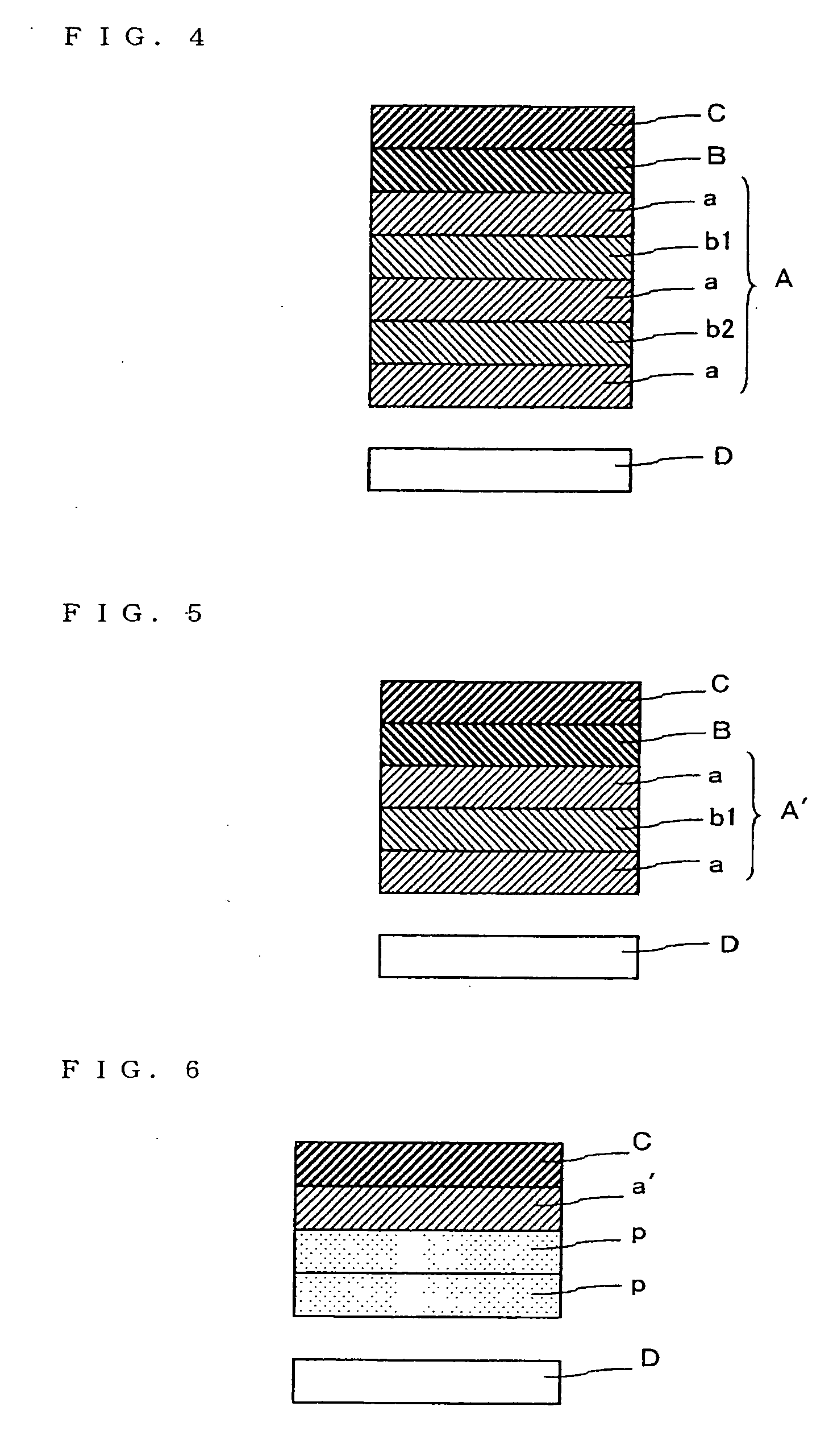
[0176] The same broadband cholesteric liquid crystal layer as in Example 1 was used as the circular-polarization-type-reflection polarizer (a). The same C-plate layer as in Example 1 was also used. However, a linear-polarization-type-reflection polarizer (DBEF manufactured by 3M) and a polycarbonate retardation plate (a λ / 4 plate) with a front retardation of 130 nm were laminated with a 5 μm-thick adhesive, and the laminate was used as the third circular-polarization-type-reflection polarizer (a) from the backlight side.
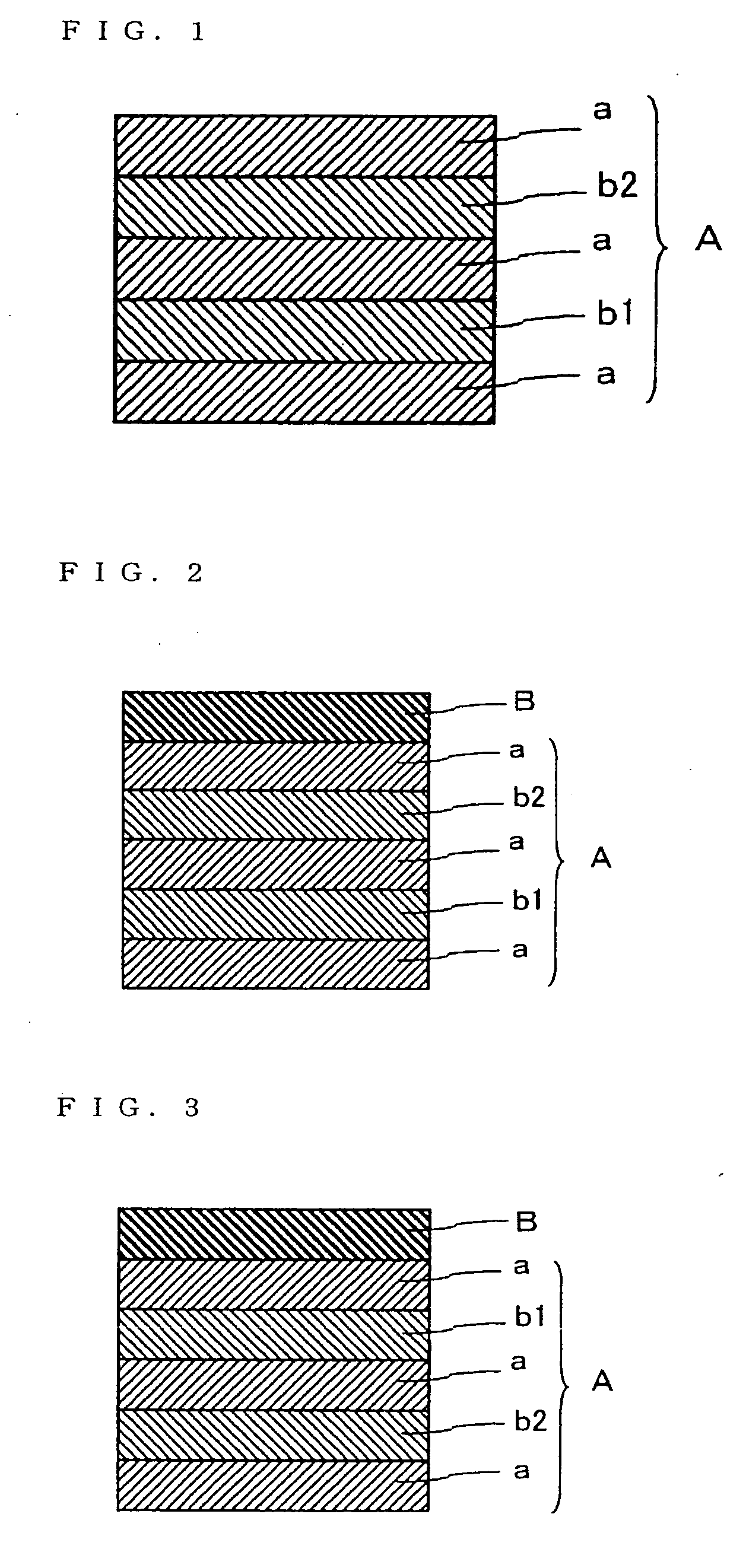
(Optical Element (A))
[0177] A piece of the same circular-polarization-type-reflection polarizer (a) as in Example 1 was placed on the backlight side in such a manner that its side having a selective reflection band on the long wavelength side faced downward. The same C-plate as in Example 1 was laminated on the polarizer (a) via a 5 μm-thick adhesive. The C-plate corresponds to the re...
PUM
| Property | Measurement | Unit |
|---|---|---|
| wavelength range | aaaaa | aaaaa |
| total thickness | aaaaa | aaaaa |
| total thickness | aaaaa | aaaaa |
Abstract
Description
Claims
Application Information