Two-phase brushless DC motor

a brushless dc motor and two-phase technology, applied in the direction of motor/generator/converter stopper, dynamo-electric converter control, magnetic circuit shape/form/construction, etc., can solve the problems of small permeance coefficient, low and inability to adapt to a large-scale motor, so as to maximize the utilization efficiency of magnetic energy of the motor, improve the feature and efficiency of large rotation torque, and minimize phase difference

Active Publication Date: 2006-11-02
BLUFFTON MOTOR WORKS
View PDF98 Cites 50 Cited by
  • Summary
  • Abstract
  • Description
  • Claims
  • Application Information

AI Technical Summary

Benefits of technology

[0024] Accordingly, the present invention has been made to overcome the conventional problems and limitations, and according to an aspect of the present invention, a two-phase brushless motor is provided which can improve large rotation torque features and efficiency by way of providing a permanent magnetic rotor having a greater number of divided poles than that of the windings of a stator to thereby maximize utilization efficiency of the magnetic energy of the motor and to minimize phase difference of the rotation driving of the motor to be 30 degrees.
[0025] Further, another aspect of the present invention is to provide a two-phase brushless motor which can utilize effective magnetic energy to the maximum by way of providing a rotor having 6×n poles, which is three times the poles of the two or three-phase motor having 2×n basic poles, to thereby increase permeance coefficient of the permanent magnet of the rotor, and by way of providing a stat

Problems solved by technology

However, since the two-phase brushless motor cannot but to be comprised of the rotor 2 having 2×n poles and a stator 1 having 4×n pole windings, the distance between poles of the permanent magnets in the rotor 2 is relatively large in comparison with that of the pole windings of the stator 1, and the pole area of the stator 1 corresponding to that of the permanent magnet of the rotor 2 is small to result in a small permeance coefficient and low utilization efficiency of the magnetic energy.
Therefore, according to thus two-phase brushless motor, it is not adaptable to a large size motor because it is great in torque ripple and small in electromotive torque.
However, although the three-phase brushless motor is more advantageous than the two-

Method used


Image

  • Two-phase brushless DC motor
  • Two-phase brushless DC motor
  • Two-phase brushless DC motor

Examples


Embodiment Construction

[0037] Reference will now be made in detail to the embodiments of the present invention, examples of which are illustrated in the accompanying drawings, wherein like reference numerals refer to the like elements throughout. The embodiments are described below to explain the present invention by referring to the figures.

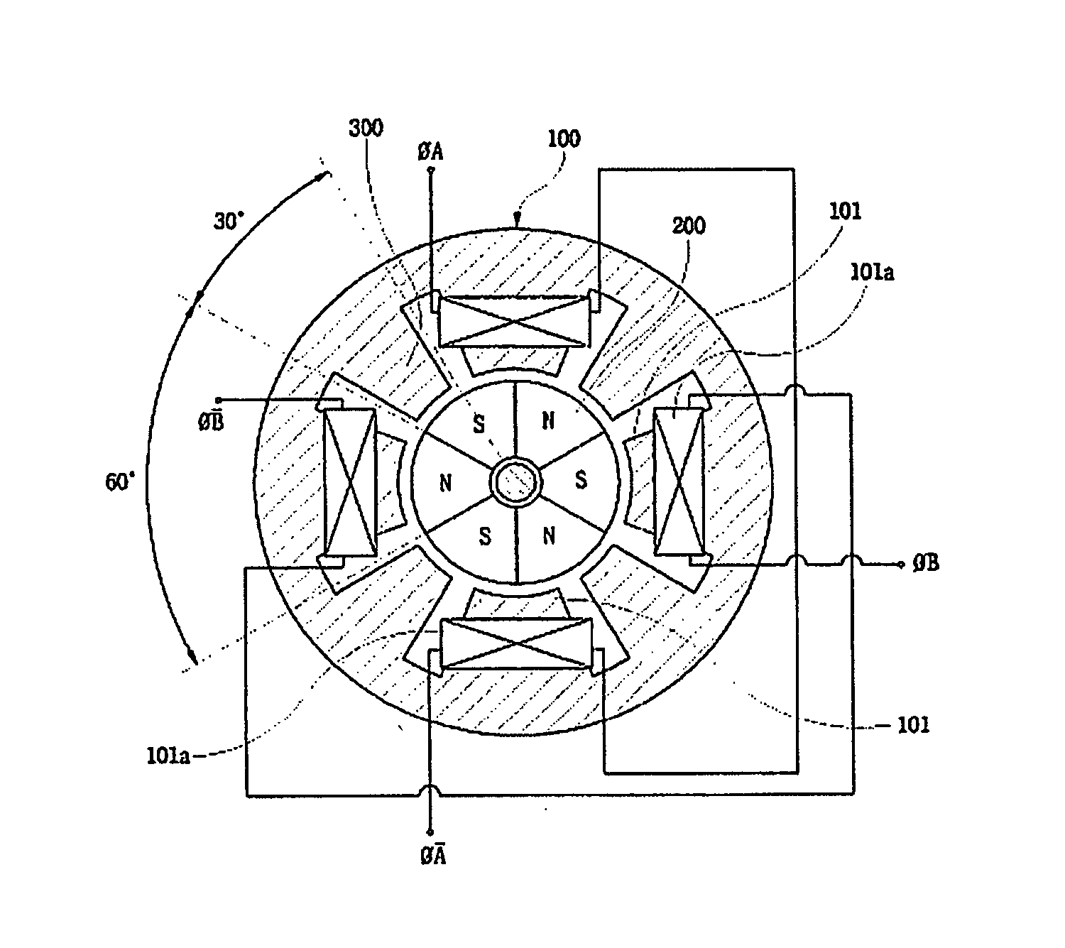
[0038] According to the present invention, there is provided a brushless motor fabricated by including a stator having 4×n poles and a permanent magnet rotor having 6×n poles, based on a motor constitution combined by a two-phase winding stator provided with four winding poles and a permanent magnet rotor provided with six poles divided into 60 divided degrees.

[0039] From now on, the constitution and action of the present invention will be described in detail in connection with FIGS. 5 to 7 showing the exemplary brushless motor including four poles stator windings and six poles rotor poles (4S6R) according to an aspect of the present invention.

[0040] As shown in FI...


PUM


Abstract

The present invention relates to a two-phase brushless DC motor which can increase a pemerance coefficient of a rotor to the maximum to thereby improve efficiency and starting feature of the motor, and to reduce torque ripple and noise thereof. The brushless motor of the present invention includes a two-phase winding stator having 4×n winding poles and auxiliary poles provided between the winding poles, and a rotor constituted by 6×n permanent magnet rotating poles having divided angle. Auxiliary poles between the stator poles can be provided. The two-phase brushless motor of the present invention can be driven by a control device for the two-phase motor which can transform electric power and rectify electronically.

Description

CROSS-REFERENCE TO RELATED APPLICATIONS [0001] This application claims the benefit of Korean Application No. 10-2005-035861 filed Apr. 29, 2005 in the Korean Intellectual Property Office, the disclosure of which is incorporated herein by reference. BACKGROUND OF THE INVENTION [0002] 1. Field of the Invention [0003] The present invention relates to a brushless motor, and in particular to a two-phase brushless DC motor, which produces rotation torque having a phase difference of 30 degrees with two-phase brushless motor driving current having 90 degrees phase difference to result in a reduction in the torque pulsation in a brushless motor and an improvement in the starting torque, and also increases a permeance coefficient of the rotor magnetic circuit over that of the brushless motor rotor having a phase difference of 60 degrees to thereby improve the efficiency of the motor. [0004] 2. Description of the Related Art [0005] In general, a brushless motor refers to a DC motor which modi...

Claims


Application Information

Patent Timeline
IPC IPC(8): H02K21/12H02K19/26
CPCH02K29/03H02K21/16H02K11/33H02K1/2753H02K15/03
Inventor JEUNG, YOUNG-CHUN
Owner BLUFFTON MOTOR WORKS
Why Eureka
Try Eureka