Digital implementation of power factor correction

a technology of power factor and digital implementation, applied in the direction of electric variable regulation, process and machine control, instruments, etc., can solve the problems of -hold (s/h) delay, not typically useful for regulating time-varying signals, and no steady-state signals for pi controllers to regula

Inactive Publication Date: 2006-11-02
INFINEON TECH AMERICAS CORP
View PDF15 Cites 77 Cited by
  • Summary
  • Abstract
  • Description
  • Claims
  • Application Information

AI Technical Summary

Benefits of technology

[0015] It is an object of the present invention to provide digital...

Problems solved by technology

PI controllers are typically good at regulating signals that have a steady state of a constant DC value, but are not typically useful for regulating a time-varying signal, such as a sinusoidal current, unless the control bandwidth of the controller is very high.
Thus, there is no steady state signal for the PI controller to regulate.
In addition, the sample-hold (S/H) delay that is inherent to the analog to digital (A/D) conversion process introduces further complications.
The phase shift will reduce the margin of the closed loop gain and affect the system stability.
However, as noted above, when the gain and bandwidth of the PI controller 26 are reduced, the PI controller will not be able to track the sinusoidal reference signal which will result in higher distortion and a lower power factor. FIGS. 5A and 5B illustrate test waveforms of a bridgeless PFC circuit using conventional digital control and a 20 kHz A/D sampling rate under heavy load (5...

Method used


Image

  • Digital implementation of power factor correction
  • Digital implementation of power factor correction
  • Digital implementation of power factor correction

Examples


Embodiment Construction

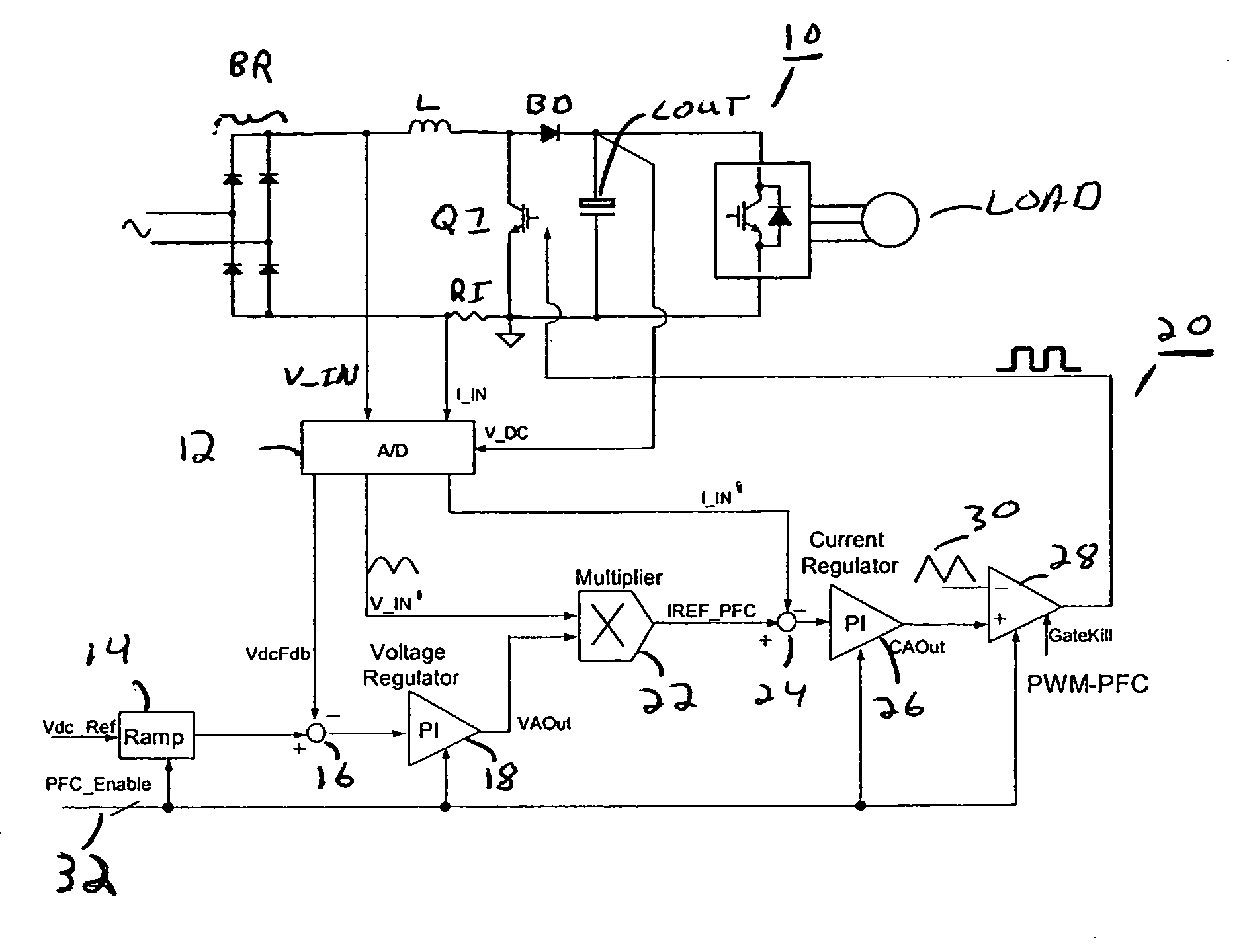
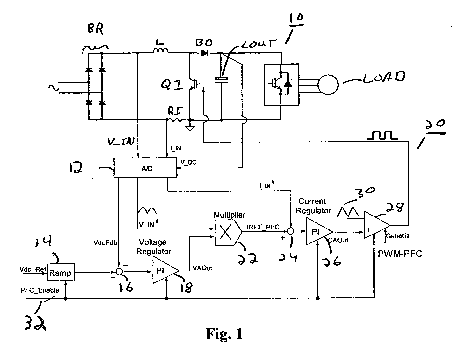
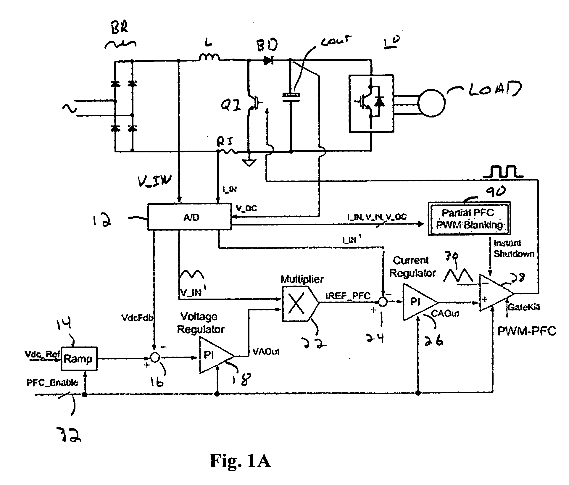
[0046] It is noted that while the PFC circuit 10 illustrated in FIG. 1 illustrates a conventional boost PFC circuit, the control concept and implementation of the present invention are similarly applicable to a bridgeless PFC circuit 10a, such as that illustrated in FIG. 2, for example. More detailed information regarding power factor correction and digital control thereof in bridgeless PFC circuits can be found in U.S. patent application Ser. No. 11 / 267,516 of Yong Li entitled DIGITAL CONTROL OF BRIDGELESS POWER FACTOR CORRECTION CIRCUIT filed on Nov. 4, 2005 and incorporated by reference herein above.

[0047] As an initial matter, the PFC current regulation loop as illustrated in FIG. 3, for example will be described, and particularly, how the current regulation is accomplished by PI controller 26. The final output of the PFC current regulation loop is the duty cycle command PWM-PFC. Utilizing PWM switching-cycle average and modeling of the PFC circuit, the instantaneous switch-on ...


PUM


Abstract

A circuit for providing power factor correction in accordance with an embodiment of the present application may include a boost converter circuit and a control circuit receiving as inputs a rectified AC input voltage from a rectifier, a signal proportional to current through the boost inductor and the DC bus voltage across the capacitor of the boost converter. The control circuit provides a pulse width modulated signal to control the on time of a PFC switch. The control circuit further includes a voltage regulator and a current regulator. The current regulator includes a difference device operable to subtract a signal proportional to the inductor current from the current reference signal, a PI controller adapted to receive the output of the difference device and provide a first control signal, a feed forward device operable to receive the rectified AC input voltage and to provide a second control signal with a smaller dynamic range than the AC input voltage, and an adder operable to add the first control signal to the second control signal to provide a PWM reference signal for generating the pulse width modulated signal. A zero crossing detector and vector rotator may be provided to provide a clean sinusoidal reference to the current regulator. A partial PFC regulator may be provide to provide partial mode PFC if desired.

Description

CROSS-REFERENCE TO RELATED APPLICATIONS [0001] This application claims benefit of a priority to Provisional Application Ser. No. 60 / 675,541 filed Apr. 28, 2005 entitled DIGITAL IMPLEMENTATION OF PFC, the entire contents of which are hereby incorporated by reference herein. [0002] This application is also related to U.S. patent application Ser. No. 11 / 267,516 entitled DIGITAL CONTROL OF BRIDGELESS POWER FACTOR CORRECTION CIRCUIT filed Nov. 4, 2005 which claims benefit of and priority to U.S. Provisional Application Ser. No. 60 / 626,117 filed Nov. 8, 2004 entitled DIGITAL CONTROL OF BRIDGELESS POWER FACTOR CORRECTION CIRCUIT, the entire contents of which are hereby incorporated by reference herein.BACKGROUND OF THE INVENTION [0003] The present application relates to power factor correction circuits, that is, circuits for reducing the distortion and harmonics generated in a power line feeding a power supply, and in particular a switch mode power supply to make the circuit, including the...

Claims


Application Information

Patent Timeline
IPC IPC(8): H02M7/04
CPCG05F1/565Y02B70/12H02M3/157H02M1/42Y02B70/10
Inventor LI, YONG
Owner INFINEON TECH AMERICAS CORP
Why Eureka
Try Eureka