Optical fiber amplifier and optical amplifying method employing it, laser oscillating method, laser amplifier and laser oscillator, and laser and laser machining apparatus both employing laser oscillator

a technology of optical amplifier and optical amplifier, which is applied in the direction of optical elements, cladded optical fibre, instruments, etc., can solve the problems of deteriorating beam quality, inability to obtain etc., and achieve the effect of efficiently ejecting high output and high beam quality laser ligh

Inactive Publication Date: 2006-11-02
PANASONIC CORP
View PDF22 Cites 7 Cited by
  • Summary
  • Abstract
  • Description
  • Claims
  • Application Information

AI Technical Summary

Benefits of technology

[0011] The laser oscillation apparatus of the present invention includes a first waveguide for transmitting excitation light; a second waveguide composed of a core containing a laser medium and generating laser light and a clad for transmitting the excitation light; and third waveguide including the first waveguide and the second waveguide. The refractive indices of the first waveguide, the clad of the second waveguide, the core of the second waveguide and the third waveguide respectively denoted by n1, n2, n3 and n4 satisfy a relation: n1<n4<n2<n3. Such a configuration can optimize the combination of a light amplifying fiber, an excitation source and a feedback means. Consequently, it is possible to provide a laser apparatus for allowing the excitation light to enter a small-diameter excitation medium efficiently and emitting high-output and high beam quality laser light efficiently.

Problems solved by technology

However, in such a case, the beam quality is deteriorated.
Therefore, a conventional laser oscillation apparatus has a problem that high output and high beam quality laser light cannot be obtained.

Method used


Image

  • Optical fiber amplifier and optical amplifying method employing it, laser oscillating method, laser amplifier and laser oscillator, and laser and laser machining apparatus both employing laser oscillator
  • Optical fiber amplifier and optical amplifying method employing it, laser oscillating method, laser amplifier and laser oscillator, and laser and laser machining apparatus both employing laser oscillator
  • Optical fiber amplifier and optical amplifying method employing it, laser oscillating method, laser amplifier and laser oscillator, and laser and laser machining apparatus both employing laser oscillator

Examples


second exemplary embodiment

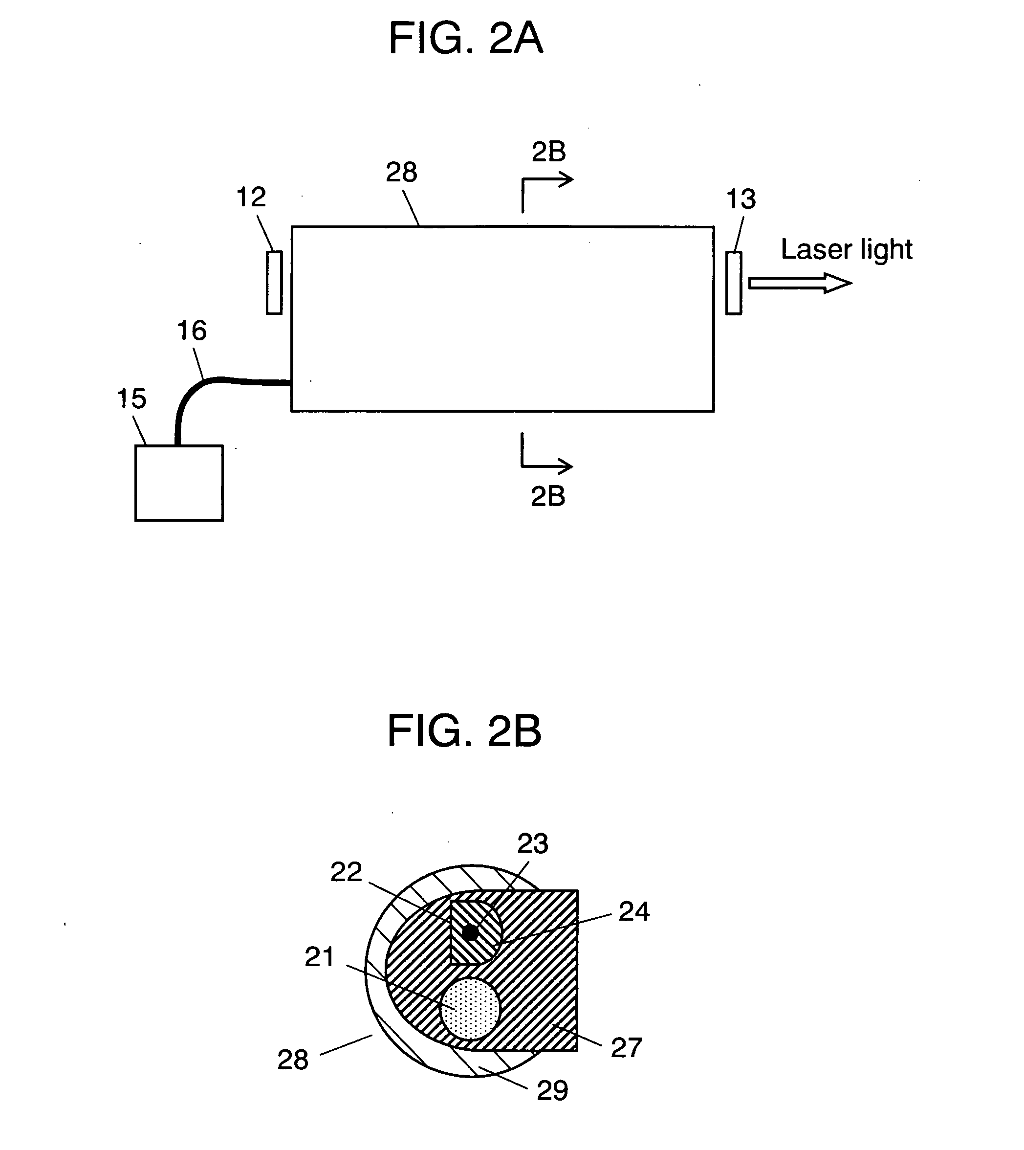
[0063]FIG. 2A illustrates a laser oscillation method and a laser oscillation apparatus using a light amplifying fiber in accordance with a second exemplary embodiment of the present invention. FIG. 2B is a sectional view taken along line 2B-2B of FIG. 2A. The same reference numerals are given to the same configuration as in the first exemplary embodiment.

[0064] The second exemplary embodiment is different from the first exemplary embodiment in that outer layer 29 of light amplifying fiber 28 has a horseshoe shape and that fluororesin is employed as a material. Furthermore, the second exemplary embodiment is different from the first exemplary embodiment in that one end of semiconductor laser 15 that is an excitation source is connected to one end of fiber 16 and another end of fiber 16 is connected to first waveguide 21 for transmitting excitation light. Furthermore, the second exemplary embodiment is different from the first exemplar embodiment in that the cross-sectional shape of ...

third exemplary embodiment

[0070]FIG. 3A illustrates a light amplifying method and a laser amplifying apparatus using a light amplifying fiber in accordance with a third exemplary embodiment of the present invention. FIG. 3B is a sectional view taken along line 3B-3B of FIG. 3A. FIG. 3C is a sectional view taken along line 3C-3C of FIG. 3A.

[0071]FIGS. 3A, 3B and 3C show semiconductor laser 14 that is an excitation source emitting laser light with the wavelength of 915 nanometers and lens 11 that is an optical element for guiding excitation light to an excitation light waveguide. Furthermore, light amplifying fiber 30 containing a laser medium in a part thereof is provided. Furthermore, FIGS. 3A, 3B and 3C show first waveguide 31 that is an excitation light waveguide, which is made of glass, has a diameter of 125 μm and transmits excitation light. FIGS. 3A, 3B and 3C also show second waveguide 32 having a D-letter shaped cross-section in the direction perpendicular to an optical axis and which absorbs excitat...

fourth exemplary embodiment

[0083]FIG. 4A illustrates a light amplifying method and a laser amplifying apparatus using a light amplifying fiber in accordance with a fourth exemplary embodiment of the present invention. FIG. 4B is a sectional view taken along line 4B-4B of FIG. 4A. FIG. 4C is a sectional view taken along line 4C-4C of FIG. 4A. In the fourth embodiment, the same reference numerals are given to the same configuration as in the third exemplary embodiment.

[0084] The fourth exemplary embodiment is different from the third exemplary embodiment in that first waveguide 31 is tilted in the direction of a laser optical axis and that the shape of third waveguide 45 is changed accordingly. Furthermore, the fourth exemplary embodiment is different from the third exemplary embodiment in that semiconductor laser 14 and lens 11 are tilted along the direction of the laser optical axis so that excitation light enters from the front surface of first waveguide 31.

[0085] In FIGS. 4A and 4B, first waveguide 31 is ...


PUM


Abstract

A small size and high efficiency laser oscillation apparatus capable of obtaining high output and high beam quality laser light is provided. First waveguide (21) (refractive index=n1) for transmitting excitation light, second waveguide (22) composed of core (23) (refractive index=n3) for generating laser light and clad (24) (refractive index=n2) for transmitting the excitation light, and third waveguide (25) (refractive index=n4) including first waveguide 21 and second waveguide 22 are provided. Light amplifying fiber (20), in which the refractive indices are set so as to satisfy the relation: n1<n4<n2<n3, is used and excised by semiconductor lasers (10a) and (10b).

Description

TECHNICAL FIELD [0001] The present invention relates to a light amplifying fiber containing a laser medium, and a light amplifying method, a laser oscillation method, a laser amplifying apparatus and a laser oscillation apparatus using the light amplifying fiber, as well as a laser apparatus and a laser processing machine using the laser oscillation apparatus. In particular, it relates to an achievement of small size and high efficiency thereof. BACKGROUND ART [0002] Recently, in the field of material processing, laser processing has been generally spread widely as one of the processing techniques. For example, it has been recognized that laser welding and laser cutting provide higher processing quality as compared with other techniques. Market demands further high quality and high speed processing and also demands a laser oscillation apparatus and a laser amplifying apparatus which generates and emits a single mode laser light having a high output property, high efficiency, and a h...

Claims


Application Information

Patent Timeline
Patent Type & Authority Applications(United States)
IPC IPC(8): G02B6/02H01S3/06H01S3/00H01S3/067H01S3/094H01S3/0941H01S3/10
CPCH01S3/06708H01S3/06729H01S3/06737H01S3/06754H01S3/06758H01S3/0941H01S3/094007H01S3/094011H01S3/094019H01S3/094042H01S3/094053H01S3/094003
Inventor NAGAYASU, DOUKEI
Owner PANASONIC CORP
Why Eureka
Try Eureka