High surface area tetragonal zirconia and processes for synthesizing same

a technology of tetragonal zirconia and high surface area, which is applied in the direction of zirconium oxides, chemistry apparatuses and processes, and oxygen/ozone/oxide/hydroxide, etc., can solve the problems of fuel cells, lack of efficient wgs catalysts, and catalysts with slow kinetics

a technology of tetragonal zirconia and high surface area, which is applied in the direction of zirconium oxides, chemistry apparatuses and processes, and oxygen/ozone/oxide/hydroxide, etc., can solve the problems of fuel cells, lack of efficient wgs catalysts, and catalysts with slow kinetics

US20060245999A1Inactive Publication Date: 2006-11-02CABOT CORP

Image

  • High surface area tetragonal zirconia and processes for synthesizing same
  • High surface area tetragonal zirconia and processes for synthesizing same
  • High surface area tetragonal zirconia and processes for synthesizing same

Examples


example 1 (

1. Example 1 (Synthesis of a—ZrO2)

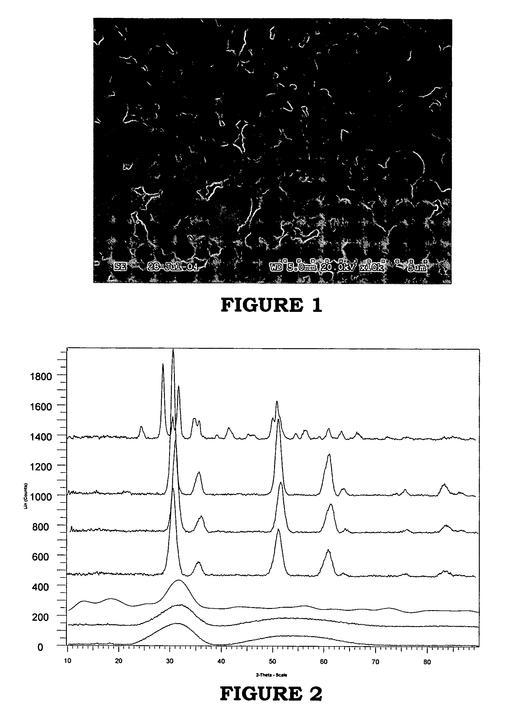
[0136] This example illustrates the production of a 20g batch of a high surface area amorphous zirconia (ZrO2) composition by precipitation of a zirconyl nitrate zirconium precursor with ammonium hydroxide followed by the digestion of zirconia hydroxide. 55 g of zirconyl nitrate (ZrO(NO3)2) was dissolved in 454 ml deionized water to obtain solution A. Solution B was prepared by mixing 100 ml deionized water and 100 ml 30 wt % ammonium hydroxide (NH4OH). Solution A was added dropwise into Solution B under vigorous stirring at room temperature to form a first precipitant. The pH was continuously monitored with a pH meter and found to decrease from 12 initially to about 9.8 at the end of precipitation. Solution C containing the above first precipitant, zirconia hydroxide, was then digested at a constant temperature of 96° C. for 192 hours to form high surface area amorphous zirconia. Additional 30 wt % NH4OH was added throughout digestion at a rate of ...


PUM


Abstract

A zirconia-containing composition and processes for synthesizing same. The composition comprises least about 99.9 percent tetragonal phase zirconia, based on the total crystalline zirconia in the zirconia-containing composition as determined by x-ray diffraction (XRD). The composition also has a substantially spherical morphology and comprises less than 100 wppm chlorine, based on the total weight of the zirconia-containing composition. The zirconia-containing composition has an average surface area of at least 80 m2 / g and an average particle size of less than about 10 microns.

Description

FIELD OF THE INVENTION [0001] The present invention relates to high surface area zirconia. More particularly, the present invention relates to high surface area tetragonal zirconia and to processes for synthesizing same. BACKGROUND OF THE INVENTION [0002] The global hydrogen market has been growing very rapidly, with recent growth rates exceeding 10% per year. Currently, about 95% of the hydrogen used today comes from the reforming of natural gas. In the near future, it is expected that the demand of hydrogen will increase due to the introduction of hydrogen fuel cells. [0003] There are three major processes for hydrogen production: steam reforming (SR) (Equation 1), partial oxidation (POX) (Equation 2) and autothermal reforming (ATR) (Equation 3), as illustrated below. Steam Reforming CH4+H2O→CO+3H2  (1) Partial Oxidation CH4+½O2→CO+2H2  (2) Autothermal Reforming 2CH4+H2O+½O2→2CO+5H2  (3) [0004] Generally, the reformate gases comprise H2, CO and CO2, H2O and a small amount of uncon...

Claims


Application Information

Patent Timeline
02 Nov 2006
Publication
US20060245999A1
IPC
C01G25/02
CPC
C01G25/02; C01P2002/72; C01P2004/03; C01P2006/80; C01P2006/14; C01P2006/16; C01P2006/12
Inventors
SHEN, JIAN-PING; FU, QI