Mechanically strong absorbent non-woven fibrous mats

a technology of fibrous mats and absorbent materials, applied in the direction of weaving, bandages, filament/thread forming, etc., can solve the problems of affecting the strength of fibrous articles, and affecting the absorption of liquid,

a technology of fibrous mats and absorbent materials, applied in the direction of weaving, bandages, filament/thread forming, etc., can solve the problems of affecting the strength of fibrous articles, and affecting the absorption of liquid,

US20060246798A1Inactive Publication Date: 2006-11-02AKRON UNIV OF

Image

  • Mechanically strong absorbent non-woven fibrous mats
  • Mechanically strong absorbent non-woven fibrous mats
  • Mechanically strong absorbent non-woven fibrous mats

Examples


examples

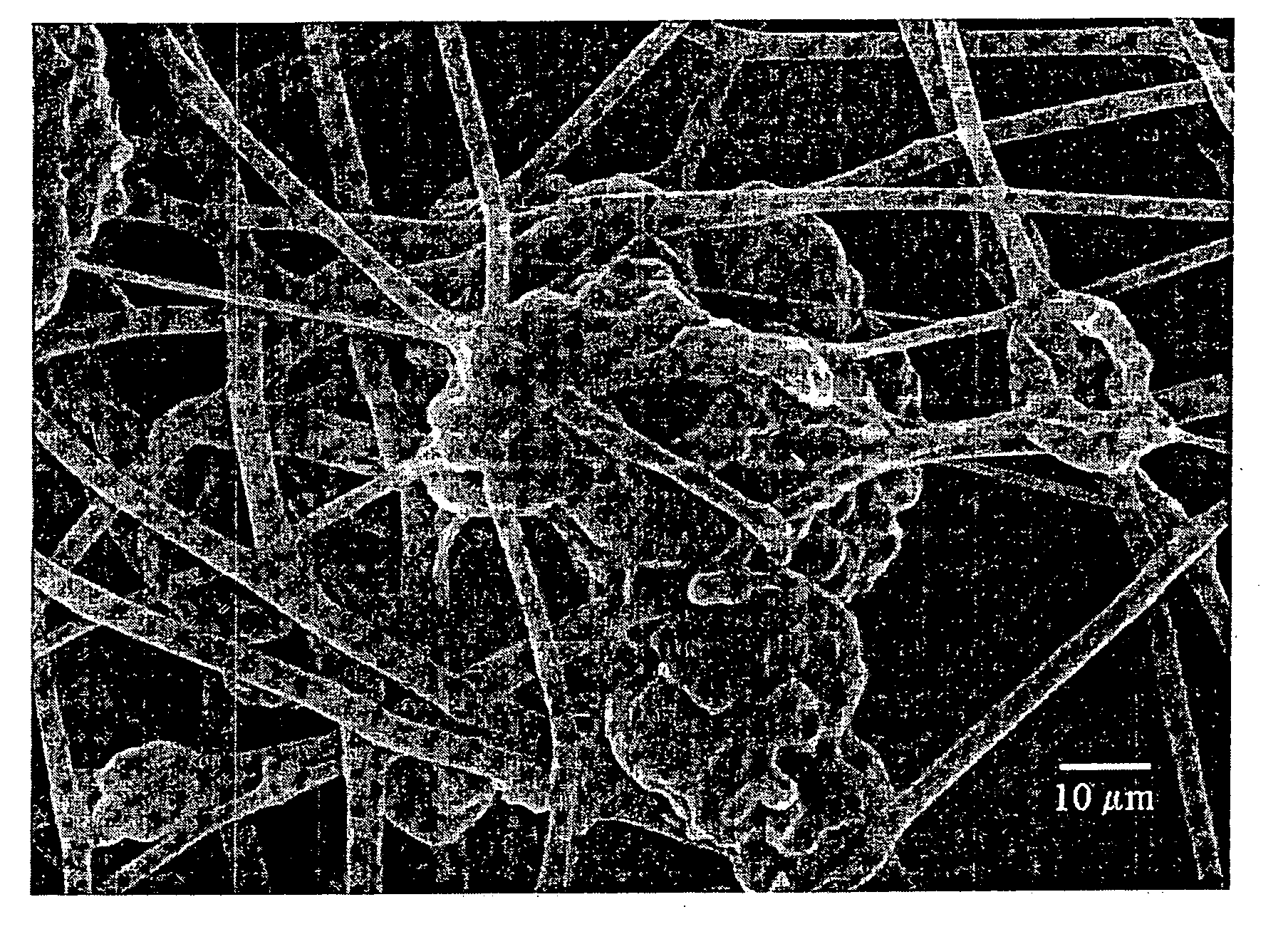
[0088] In order to demonstrate the practice of the present invention the following examples have been prepared. Composite fibers are electrospun from a THF:ethanol solution (30:70) containing Waterlock® A-180 and Tecophilic® polymers to form non-woven fiber assemblies or mats. Waterlock® polymers are corn starch / acrylamide / sodium acrylate copolymers available from Grain Processing Corp. (Muscatine, Iowa). Waterlock® polymers contribute a hydrophilic component to the resulting fiber assembly. Tecophilic® is an aliphatic polyether-based polyurethane available from Thermedics Polymer Products (Wilmington, Mass.), which contributes an elastomeric component and a hydrophilic component to the fiber assembly.

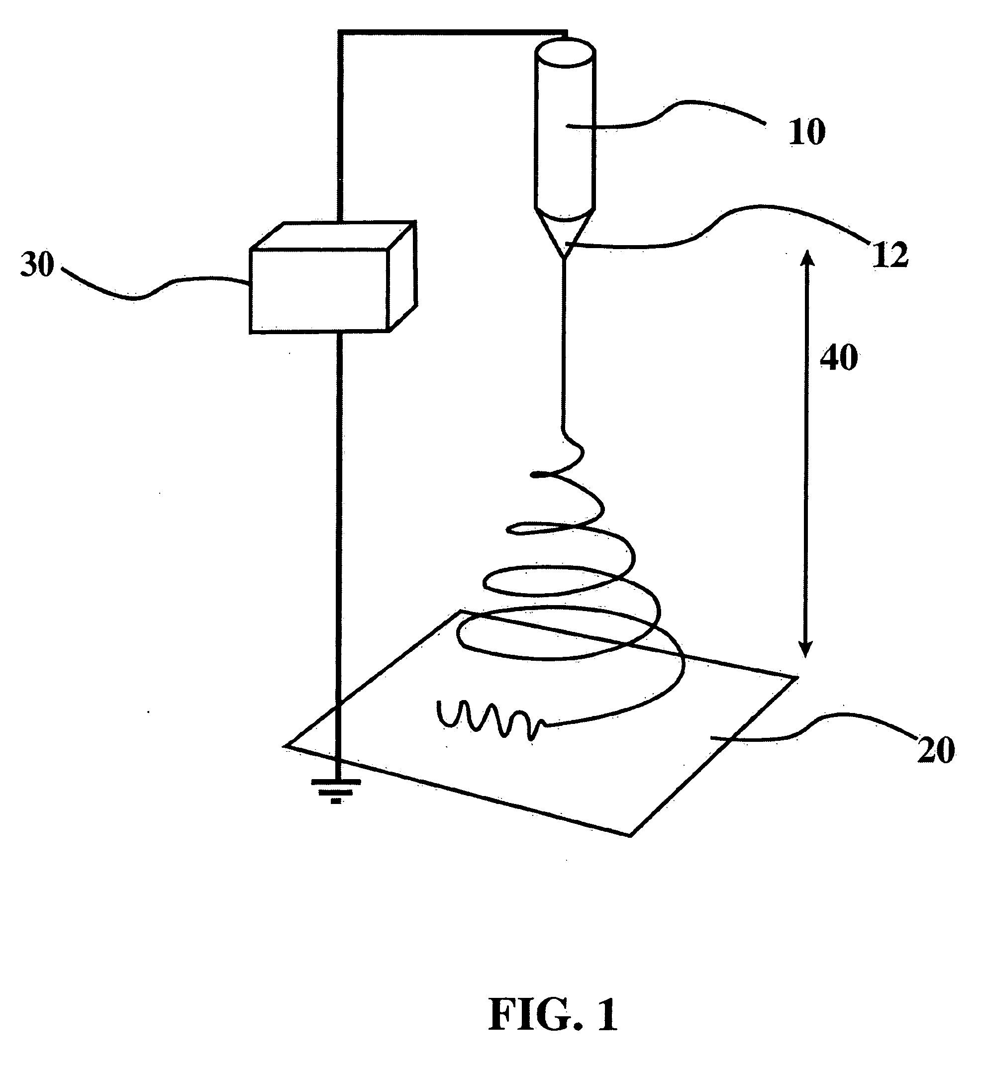
[0089] The polymer solutions are spun from a conical metal reservoir, and the gap distance is varied with a laboratory jack. The metal cone is suspended with metal wire connected to a high voltage power supply. The voltage and gap distance are varied to produce the best fibers at the ...


PUM

PropertyMeasurementUnit
Fractionaaaaaaaaaa
Fractionaaaaaaaaaa
Fractionaaaaaaaaaa

Abstract

The present invention is generally directed to a liquid entrapping device having the capacity to absorb liquids. More particularly, the present invention is directed to a liquid entrapping device comprising an absorbent component, hydrophilic elastomeric fibrous component in fluid communication therewith, and optionally an adhesive component. The present invention is also directed to a liquid entrapping device having the capacity to absorb liquids while maintaining a suitable degree of mechanical strength. Furthermore, the present invention is generally directed to methods for making and using the foregoing devices and materials.

Description

RELATED APPLICATION DATA [0001] This application is both (1) a continuation of U.S. Provisional Application No. 60 / 681,544 filed May 16, 2005; and (2) a continuation-in-part of Ser. No. 10 / 510,457 filed Oct. 4, 2004; which is a national phase application of PCT / US03 / 10652 filed Apr. 4, 2003; which claims priority to U.S. Provisional Application No. 60 / 370,051 filed Apr. 4, 2002; each of which are hereby incorporated herein by reference in their entireties.BACKGROUND OF THE INVENTION [0002] The present invention relates to mechanically strong absorbent materials. More particularly such materials comprise at least one hydrophilic elastomeric fibrous component (HEFC) and at least one absorbent component. Additionally, some embodiments can further comprise an adhesive component. The HEFC can comprise a block copolymer wherein the blocks comprise an elastomeric block and a hydrophilic block. Alternatively, the HEFC can comprise a mixture or solid solution of hydrophilic polymer and elast...

Claims


Application Information

Patent Timeline
02 Nov 2006
Publication
US20060246798A1
IPC
B32B5/02
CPC
A61F13/531; A61F2013/530299; A61F2013/53791; A61L15/225; A61L26/0052; D01D5/0038; D01F1/10; D01F6/88
Inventors
RENEKER, DARRELL; SMITH, DANIEL