Method and apparatus for electronics cooling

a technology for electronics and cooling, applied in lighting and heating apparatus, semiconductor/solid-state device details, laminated elements, etc., can solve the problems of inefficient refrigeration methods, more input power than can be dissipated, and heat emitted by these circuits can overwhelm the cooling capacity of conventional air-blown heat sinks

Inactive Publication Date: 2006-11-09
CHORDIA LALIT +4
View PDF18 Cites 20 Cited by
  • Summary
  • Abstract
  • Description
  • Claims
  • Application Information

AI Technical Summary

Benefits of technology

[0014] This method allows heat to be removed from multiple sources on the circuit board.

Problems solved by technology

The heat emitted by these circuits can overwhelm the cooling capacity of conventional air-blown heat sinks, especially for example in the cases of thin-profile apparatuses such as laptop computers and stacked server boards.
However, Peltier coolers require more input power than can be dissipated and are therefore an inefficient means of refrigeration because more heat is added than is removed.
All of these inventions are limited by the thermal conductivity of the transporting media, which in turn is limited by the temperature difference that can be achieved between the conductive media and cooling air.
This system, however, is based on different densities of the fluid, depending on pressure, and thus is pressure-dependent.
Because Takeda et al. has no means for propelling the fluid the system is limited in its capacity.
Furthermore, the system is limited in its physical configuration in that it must maintain a particular orientation with respect to the earth's center of gravity.

Method used


Image

  • Method and apparatus for electronics cooling
  • Method and apparatus for electronics cooling
  • Method and apparatus for electronics cooling

Examples


example 3

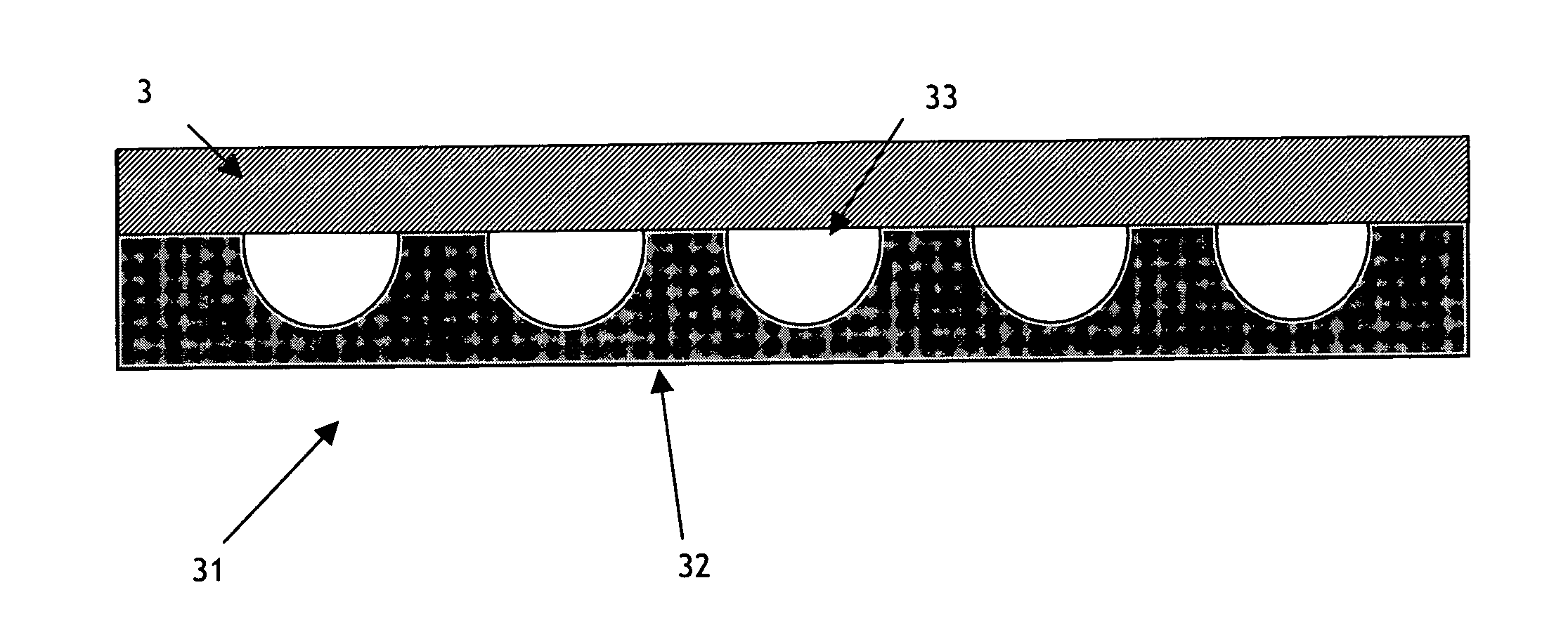
[0057] A heat accepting heat exchanger measuring 100×100 millimeters square and 0.011 inches in thickness is constructed with an array of 80 microchannels running through the center of the lamination, from one side to the opposite side, and laminated into a printed circuit board configuration of layers with FR-4 epoxy insulation. The channels measured nominally 200 microns wide by 100 microns deep and were separated by a distance of nominally 100 microns. In the center of the board was a heat source measuring 27×27 millimeters. The heat accepting heat exchanger was separated from direct contact with the heat source by the distance of one layer of FR-4 but was in indirect contact with the heat source through a square array of 81 thermal vias.

[0058] Heat emitted by the heater was from 15-55 watts. Carbon dioxide from a pressurized tank was directed into this heat accepting heat exchanger by a fluid driver at 84 bar and 37° C. inlet temperature, and at flow rates ranging between 0.18 ...


PUM


Abstract

A method and apparatus for actively cooling a device, space or circuit board are disclosed. The device may be an electrical or electronic component that includes an integrated circuit or embedded control. The apparatus employs a fluid in a closed loop, at least two heat exchangers and a fluid driver.

Description

CROSS-REFERENCE TO RELATED APPLICATIONS: [0001] This application is a continuation-in-part of U.S. non-provisional patent application Ser. No. 10 / 702,396 filed on Nov. 5, 2003, which itself claims priority to U.S. provisional patent application Ser. No. 60 / 424,142 filed Nov. 5, 2002. This application also claims priority to U.S. non-provisional patent application Ser. No. 11 / 198,889 filed Aug. 5, 2005, which is also a continuation-in-part of U.S. non-provisional patent application Ser. No. 10 / 702,396. All of the above-referenced applications are incorporated herein by reference.FIELD OF THE INVENTION [0002] The invention generally relates to cooling systems and more particularly relates to an active cooling system and method that employs a fluid near or above its critical pressure, and also relates to a small-scale apparatus utilized to operate such a cycle. Typical target applications include, for example, cooling of printed circuit boards, computers, computer components, analytica...

Claims


Application Information

Patent Timeline
Patent Type & Authority Applications(United States)
IPC IPC(8): H05K7/20F28D15/02F28F3/12H01L23/473
CPCF25B2309/061F28D15/0266F28F3/12F28F2260/02H01L2924/0002H01L23/473H01L2924/00
Inventor CHORDIA, LALITDAVIS, JOHNFATSCHEL, STEPHANPANELLA, ROBERTMOYER, BRIAN
Owner CHORDIA LALIT
Why Eureka
Try Eureka