Magnesium oxide-containing barrier layer for thick dielectric electroluminescent displays

Inactive Publication Date: 2006-11-09
SANYO ELECTRIC CO LTD +1
View PDF29 Cites 7 Cited by
  • Summary
  • Abstract
  • Description
  • Claims
  • Application Information

AI Technical Summary

Benefits of technology

[0007] The present invention provides an improved operating life to a thin film alkaline earth thioaluminate phosphor doped with a rare earth activator species. The improved operating life is achieved by providing a magnesium oxide or magnesium oxide containing barrier layer directly in contact with the bottom portion of the phosphor. The magnesium oxide or magnesium oxide containing barrier la

Problems solved by technology

However, the operating stability still falls short of that provided by CRTs.
Alumina layers have been used to provide a measure of chemical isolation between thick dielectric layers and phosphor layer, however, their effectiveness is reduced wh

Method used


Image

  • Magnesium oxide-containing barrier layer for thick dielectric electroluminescent displays
  • Magnesium oxide-containing barrier layer for thick dielectric electroluminescent displays
  • Magnesium oxide-containing barrier layer for thick dielectric electroluminescent displays

Examples


example 1

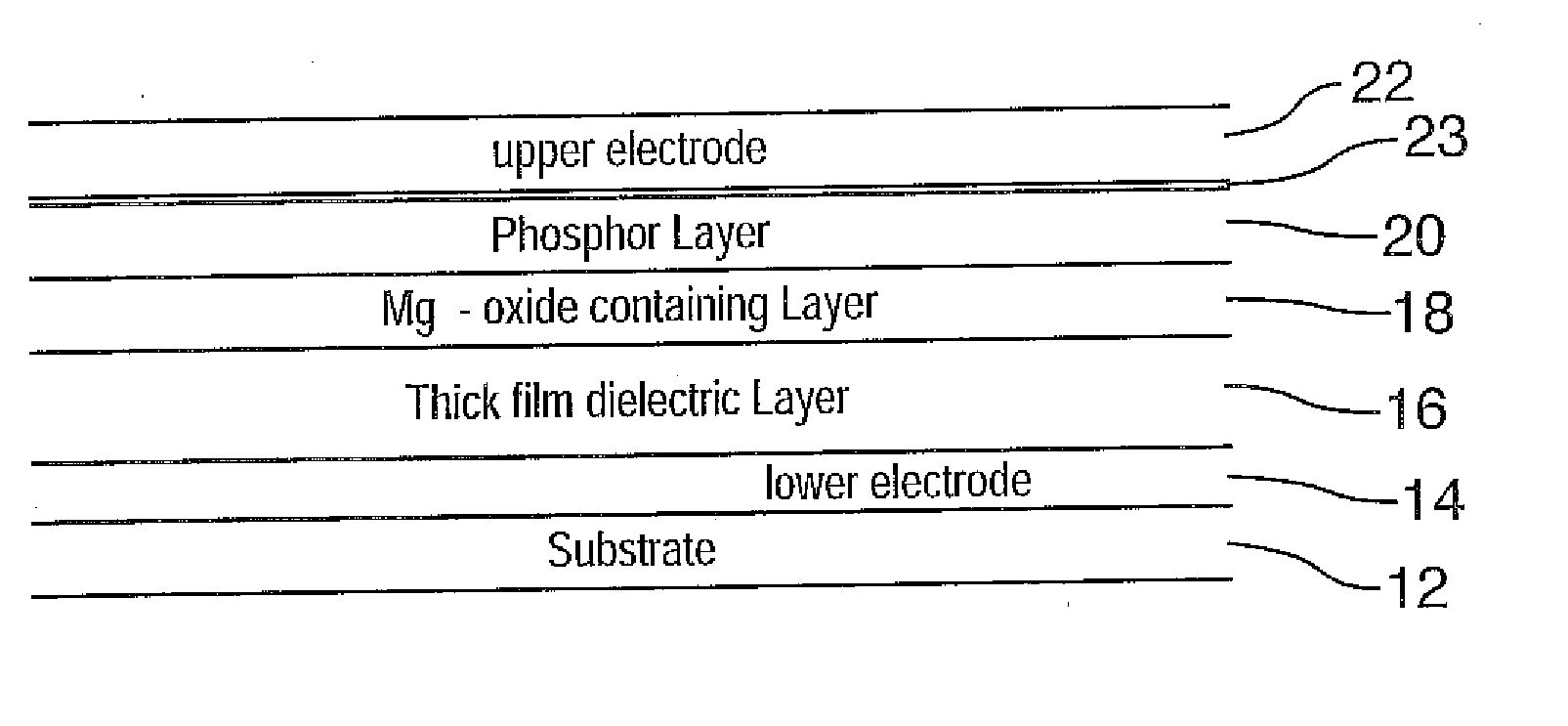
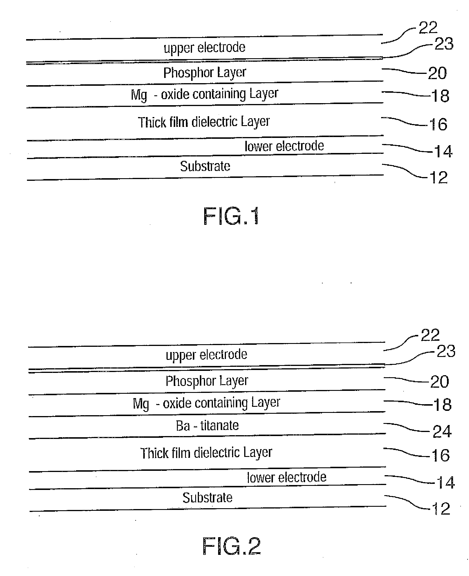
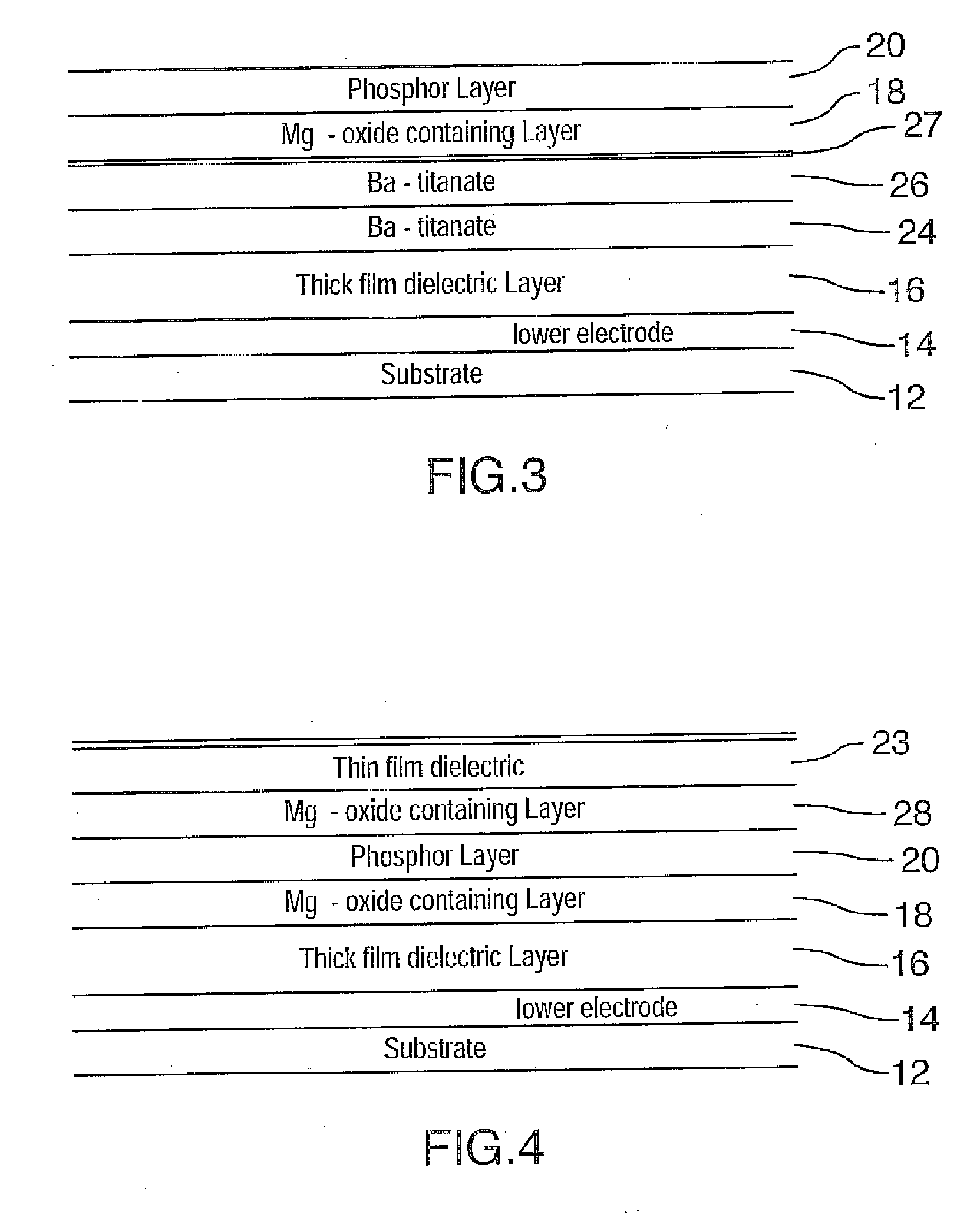
[0073] This example serves to illustrate the performance and operating stability of devices of the prior art. A thick dielectric electroluminescent device incorporating thin film phosphor layers comprising barium thioaluminate activated with europium was constructed. The thick film substrate was comprised of a 5 cm by 5 cm glass having a thickness of 0.1 cm. A gold electrode was deposited on the substrate, followed with a lead magnesium niobate-titanate thick film high dielectric constant dielectric layer and a PZT smoothing layer in accordance with the methods exemplified in Applicant's co-pending International Patent Application WO 00 / 70917 filed May 12, 2000. A thin film dielectric layer consisting of barium titanate with a thickness of about 170 nanometers was deposited in accordance with the methods exemplified in U.S. Pat. No. 6,589,674 (the entirety of which is incorporated herein by reference). A second thin film layer consisting of barium tantalate with a thickness of 50 na...

example 2

[0075] This example serves to illustrate the benefit of the invention. A device was constructed similar to that of example 1, except that a 37 nanometer thick magnesium oxide layer was sputter deposited on top of the alumina layer prior to phosphor deposition. The luminance data for this device tested under the same conditions as for the device of example 1 is also shown in FIG. 6 (solid diamonds) and shows an initial luminance of about 173 candelas per square meter, followed by a slow rate of luminance loss. The luminance after 1100 hours of operation was still about 87 candelas per square meter.

example 3

[0076] This example serves to illustrate the benefit of the invention to improve operating stability in an electroluminescent device with a different phosphor composition. FIG. 7 shows the luminance as a function of operating time for a device similar to that of example 2 except that it had a phosphor composition with a europium concentration of about 6 atomic percent of europium with respect to barium (open circles). FIG. 7 also shows the luminance as a function of operating time for a similar device with a 37 nanometer thick magnesium oxide layer between the alumina layer and the phosphor layer. The initial luminance of these two devices was very similar at about 100 candelas per square meter). The luminance of the device without the magnesium oxide layer dropped to 48 candelas per square meter after 570 hours of operation, while the luminance of the other device with the magnesium oxide layer was still above 80 candelas per square meter after 1400 hours of operation.


PUM


Abstract

A novel laminate is provided to improve the operating stability of thioaluminate based phosphors used in ac thick film dielectric electroluminescent displays. The novel structure comprises a rare earth activated alkaline earth thioaluminate phosphor thin film layer and a magnesium oxide or magnesium oxide containing layer provided directly adjacent and in contact with the bottom of the phosphor thin film layer. The invention is particularly applicable to phosphors used in electroluminescent displays that employ thick dielectric layers subject to high processing temperatures to form and activate the phosphor films.

Description

FIELD OF THE INVENTION [0001] The invention is directed to improving the luminance and operating stability of phosphors used for full color ac electroluminescent displays employing thick film dielectric layers with a high dielectric constant. More specifically, the invention provides magnesium-oxide containing layers in contact with the phosphor layer to prevent phosphor degradation. BACKGROUND OF THE INVENTION [0002] The thick film dielectric structure provides for superior resistance to dielectric breakdown as well as a reduced operating voltage as compared to thin film electroluminescent (TFEL) displays, as exemplified by U.S. Pat. No. 5,432,015. The thick film dielectric structure also enhances the amount of charge that can be injected in to the phosphor film to provide greater luminosity than can be realized from TFEL displays. Full colour thick dielectric electroluminescent displays are described for example in the Applicant's co-pending International Patent Application WO 200...

Claims


Application Information

Patent Timeline
IPC IPC(8): H01J1/62H01J63/04
CPCC09K11/7734H05B33/22H05B33/14
Inventor YOSHIDA, ISAOHAMADA, HIROKIACCHIONE, JOEXIN, YONGBAOYU, SAN
Owner SANYO ELECTRIC CO LTD
Why Eureka
Try Eureka