Combined cycle power plant using compressor air extraction

a technology of compressor air extraction and power plant, which is applied in the direction of machines/engines, mechanical equipment, engine starters, etc., can solve the problems of increasing installation, operation and maintenance costs, and the use of auxiliary boilers

Inactive Publication Date: 2006-11-16
SIEMENS ENERGY INC
View PDF21 Cites 47 Cited by
  • Summary
  • Abstract
  • Description
  • Claims
  • Application Information

AI Technical Summary

Problems solved by technology

Steam is available from the heat recovery steam generator of a combined cycle plant only after a considerable delay due to thermal lag and thermal stress limitations inherent in the system.
While the use of auxiliary boiler steam provides a benefit by reducing the start-up time for a combined cycle power plant, the use of an auxiliary boiler increases installation, operation and maintenance costs.

Method used


Image

  • Combined cycle power plant using compressor air extraction
  • Combined cycle power plant using compressor air extraction

Examples


Embodiment Construction

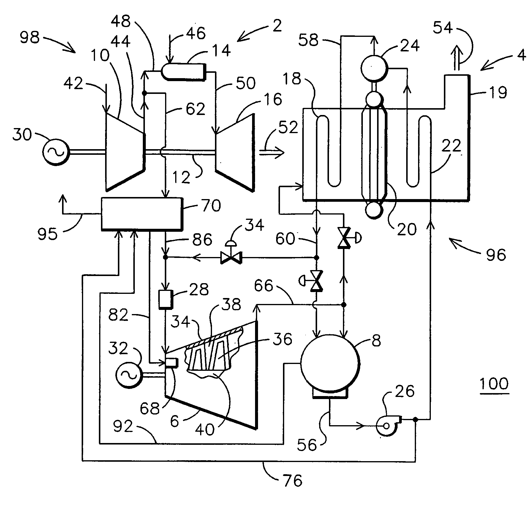
[0008] Referring to the drawings, there is shown in FIG. 1 a schematic diagram of a combined cycle power plant 100 including a gas portion 98 and a steam portion 96. The major components of the power plant include a gas turbine engine 2, a heat recovery steam generator (HRSG) 4, a steam turbine 6, and a condenser 8. The gas turbine engine 2 includes a compressor 10, a gas turbine section 16 having a rotor shaft 12 connected to the compressor 10 and to an electrical generator 30, and a combustor 14. The HRSG 4 includes a superheater 18, an evaporator 20, a steam drum 24, and an economizer 22. The steam turbine 6 includes a rotor 40 mounted for rotation within a casing 34 so as to form a flow path for the steam there between. Gland seals 68 prevent the working fluid steam from escaping from the steam flow path. As is conventional, a plurality of the rotating blades 36 and stationary vanes 38 project into the flow path.

[0009] In operation, the compressor 10 inducts ambient air 42 and ...


PUM


Abstract

A combined cycle power plant (100) utilizing a compressor air bleed (62) as a source of heat for generating steam in a steam generator (78) for supplying the gland seals of the steam turbine (3) and as a motive force for an air ejector (90) for evacuating the condenser (8) during plant start-up. The compressor air bleed avoids delay awaiting the availability of steam from the heat recovery steam generator (4) without the need for an auxiliary boiler.

Description

FIELD OF THE INVENTION [0001] This invention relates generally to the field of combined cycle power plants. BACKGROUND OF THE INVENTION [0002] Combined cycle power plants are known to include a gas portion and a steam portion. The gas portion includes a gas turbine engine powered by the combustion of a fuel such as natural gas or fuel oil. A steam turbine of the steam portion is powered by steam that is generated by the cooling of the gas turbine exhaust in a heat recovery steam generator (HRSG). The gas turbine and the steam turbine typically provide shaft power for one or more electrical generators. [0003] The steam portion includes a condenser for converting expanded steam received from the outlet of the steam turbine into condensate for delivery to the heat recovery steam generator. A vacuum is maintained in the condenser during operation by the condensation of steam. During start-up of the plant, the condenser vacuum is established by operating a vacuum pump, such as a mechanic...

Claims


Application Information

Patent Timeline
Patent Type & Authority Applications(United States)
IPC IPC(8): F02C6/18
CPCF01D19/00F02C6/18F02C9/18F05D2260/85F05D2220/74F05D2240/55F05D2220/72Y02E20/16
Inventor BRIESCH, MICHAELSCHMEDEMAN, ANDREWSCHMID, ERICH
Owner SIEMENS ENERGY INC
Why Eureka
Try Eureka