Thermally stable diamond brazing

Inactive Publication Date: 2006-11-16
RADTKE ROBERT P
View PDF11 Cites 158 Cited by
  • Summary
  • Abstract
  • Description
  • Claims
  • Application Information

AI Technical Summary

Benefits of technology

[0015] In one aspect, the present invention relates to a cutting element that includes a substrate, a TSP diamond layer, a metal interlayer between the substrate

Problems solved by technology

Drill bits using conventional PDC cutters are sometimes unable to sustain a sufficiently low wear rate at the cutter temperatures generally encountered while drilling in abrasive and hard rock.
These temperatures may affect the bit life, especially when the temperatures reach 700-750° C., resulting in structural failure of the PDC cutting layer.
Therefore, upon heating of a diamond table, the cobalt and the diamond lattice will expand at different rates, causing cracks to form in the lattice structure and resulting in deterioration of the diamond table.
However, because TSP is made by removing cobalt from the diamond layer, attachment

Method used


Image

  • Thermally stable diamond brazing
  • Thermally stable diamond brazing
  • Thermally stable diamond brazing

Examples


Embodiment Construction

[0027] In one aspect, embodiments of the invention relate to a cutting element having a diamond layer brazed to a substrate. In particular, embodiments relate to a cutting element having a braze joint with a high shear strength. Moreover, embodiments relate to a method for forming such cutting elements.

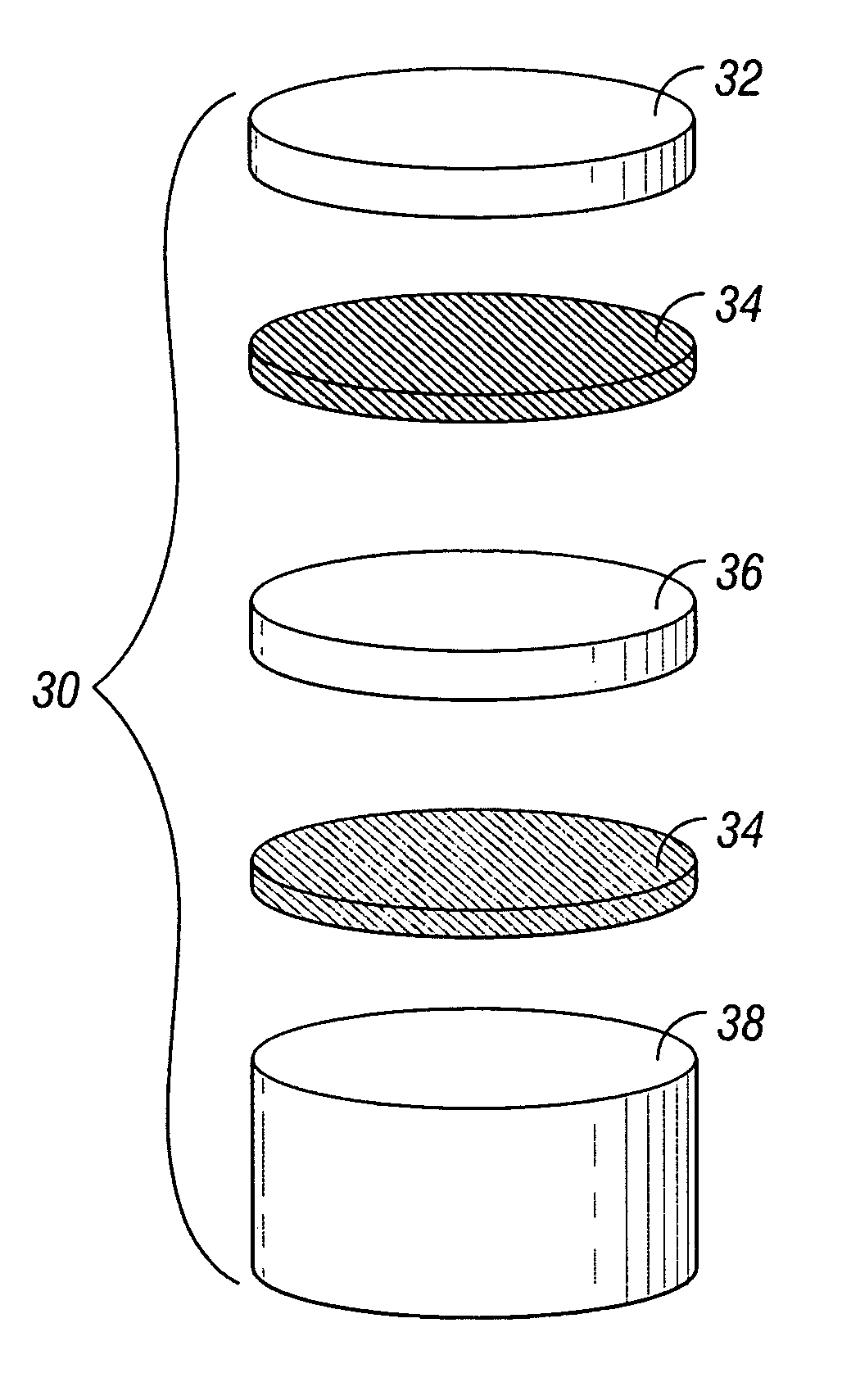
[0028] Referring to FIG. 3, a cutter assembly is shown used to make a cutting element according to one embodiment of the present invention. The cutter assembly 30 includes a co-axial stack of a TSP diamond layer 32, braze layers 34, a metal interlayer 36, and a substrate 38. Upon treatment of the cutter assembly 30, a cutting element may be formed when the braze layers 34 are melted and join together the TSP diamond layer 32, the metal interlayer 36, and the substrate 38, forming a braze joint (not shown separately). It may become apparent to anyone skilled in the art that these metal interlayers 36 become effective shock absorbing materials that can be applied to all cutting element...


PUM

PropertyMeasurementUnit
Timeaaaaaaaaaa
Timeaaaaaaaaaa
Thicknessaaaaaaaaaa

Abstract

A cutting element and a method for forming a cutting element is described and shown. The cutting element includes a substrate, a TSP diamond layer, a metal interlayer between the substrate and the diamond layer, and a braze joint securing the diamond layer to the substrate.

Description

BACKGROUND OF INVENTION [0001] 1. Field of the Invention [0002] The invention relates generally to drill bits which have polycrystalline diamond compact cutters thereon. [0003] 2. Background Art [0004] Polycrystalline diamond compact (PDC) cutters have been used in industrial applications including wellbore drilling and metal machining for many years. In these applications, a compact of polycrystalline diamond (or other superhard material such as cubic boron nitride) is bonded to a substrate material, which is typically a sintered metal-carbide, to form a cutting structure. A compact is a polycrystalline mass of diamonds (typically synthetic) that are bonded together to form an integral, tough, high-strength mass. [0005] An example of a use of PDC cutters is in a drill bit for earth formation drilling is disclosed in U.S. Pat. No.5,186,268. FIG. 1 in the '268 patent shows a cross-section of a rotary drill bit having a bit body 10. A lower face of the bit body 10 is formed to include...

Claims


Application Information

Patent Timeline
IPC IPC(8): E21B10/36
CPCE21B10/5735B23K1/0008B23K31/025B23K2103/18B23K2103/50B23K2103/52B23K1/0006B23K35/001B23K35/3033
Inventor RADTKE, ROBERT P.
Owner RADTKE ROBERT P
Why Eureka
Try Eureka