Compact, economical, multi-axis, multi-tasking, small part machine tool

a multi-tasking, compact technology, applied in the field of compact, multi-axis, multi-tasking small part machine tools, can solve the problems of increasing the demand for making things smaller, affecting the quality of small parts, and the inability of milling machines to radially symmetrical surfaces with high precision, so as to prevent damage to tools and reduce interference with tool changing.

Inactive Publication Date: 2006-11-16
MILLER LEE NORRIS
View PDF8 Cites 10 Cited by
  • Summary
  • Abstract
  • Description
  • Claims
  • Application Information

AI Technical Summary

Benefits of technology

[0012] It is therefore an object of the present invention to provide a compact, economical, and easy-to-use small parts machine tool that could machine small parts from bar stock as well as castings, forgings, slugs, and near net shape raw materials.
[0014] According to the present invention, the machine tool includes a base comprising an arrangement such as a chuck, often referred to as a spindle, for moving or positioning a workpiece rotationally about an axis with respect to the length of the base (C coordinate direction). Preferably, the base further comprises a sliding means that mounts or otherwise connects to slides formed on a first carriage (Z carriage). When connected, the Z carriage moves in a reciprocal direction along the length of the base (Z coordinate direction). Preferably, the Z carriage also includes a sliding means that mounts or otherwise connects to slides formed on a second carriage (Y carriage). When connected, the Y carriage moves in a vertical reciprocal direction (Y coordinate direction). Further, the Y carriage also includes a sliding means that mounts or otherwise connects to slides formed on a third carriage (X carriage). When connected, the X carriage moves in a horizontal reciprocal direction (X coordinate direction). Lastly, the X carriage includes grooves, “T” slots or a series of tapped holes that supports a tool holder system. Because the machine preferably incorporates only four axes (i.e., X, Y, Z, and C), cost of assembly, as well as size, is greatly reduced as compared to the prior art discussed above. The machine can also be manufactured with a fifth axis wherein one or more tools are moved rotationally about an axis preferably parallel to the X carriage movement and in a direction perpendicular to the length of the X carriage (A coordinate direction). This can be accomplished either by tilting the X carriage, thus tilting all tools attached to a particular tool block, or by tilting the tools themselves.
[0016] The tool blocks are connected to or assembled using grooves, “T” slots or a series of tapped holes on the X carriage and are placed above the workpiece to be machined. Because of this placement, nothing is below the workpiece. Accordingly, shavings fall to the ground thus preventing damage to the tools. Interference with tool changing is also reduced due to the placement of the tool blocks in accordance with the present invention.

Problems solved by technology

Regardless of the industry, the demand for making things smaller is growing rapidly and manufacturers face continual challenges in making small components.
However, milling machines are not well-suited to forming radially symmetrical surfaces with high precision.
Because many lathes used to machine small parts are primarily intended for hobby shop or home shop machining, they are not well suited for industrial applications.
However, for smaller components, handling, re-orienting, and re-fixturing and / or chucking the part for a second or third machining operation becomes extremely difficult and a source of potential error or inaccuracy.
Although industrial machines do exist that perform both types of operations, such as CNC controlled Swiss-type machines for small parts, these machines often require multiple duplicate axes to perform these additional operations.
This requirement tends to sacrifice simplicity for higher production rates and / or the ability to multi-task.
However, market demand for product customization often supplants the need for higher production rates and thus increases the importance of simplicity, flexibility, and reduced set-up times. Furthermore, in large part due to their numerous axes, Swiss-type machines are quite expensive.
Further, manufacturers may also be restricted by the type of raw material they may use when machining small parts.
For example, since the operation of Swiss-type screw machine depends on the utilization of bar stock as the raw material, this precludes manufacturers who are utilizing these machines from manufacturing small parts formed by castings, forgings, sawed bar stock slugs, or newer, near net shape raw material alternatives (e.g. metal injection moldings).
At this reduced scale, cutting tools and tool holders tend to interfere with work holding devices, other cutting tools or tool holders, or parts of the machine tool itself.
This leads to the possibility of tool and workpiece flexing, vibration, breaking, etc.

Method used


Image

  • Compact, economical, multi-axis, multi-tasking, small part machine tool
  • Compact, economical, multi-axis, multi-tasking, small part machine tool
  • Compact, economical, multi-axis, multi-tasking, small part machine tool

Examples


Embodiment Construction

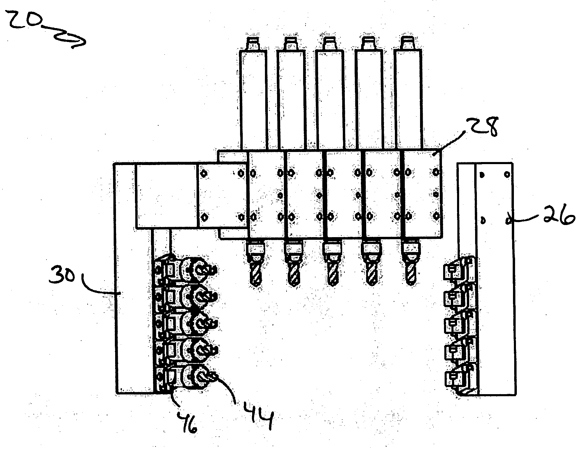
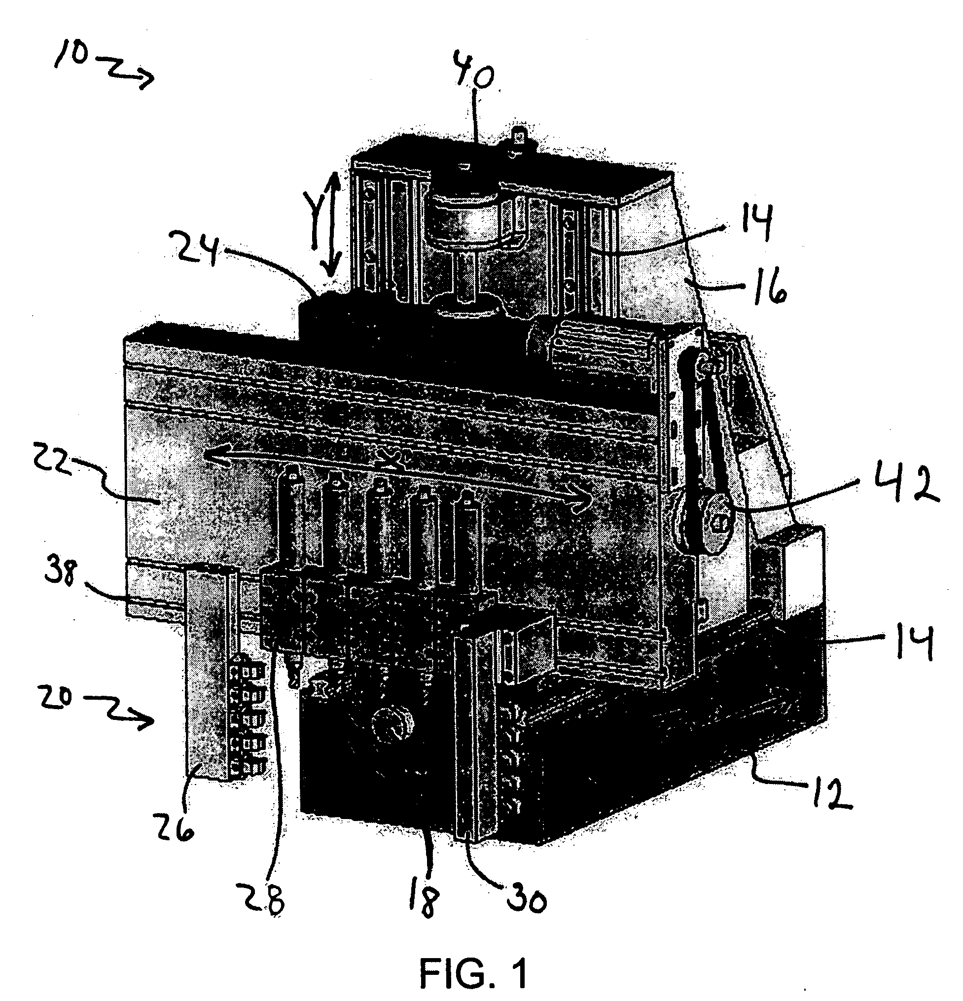
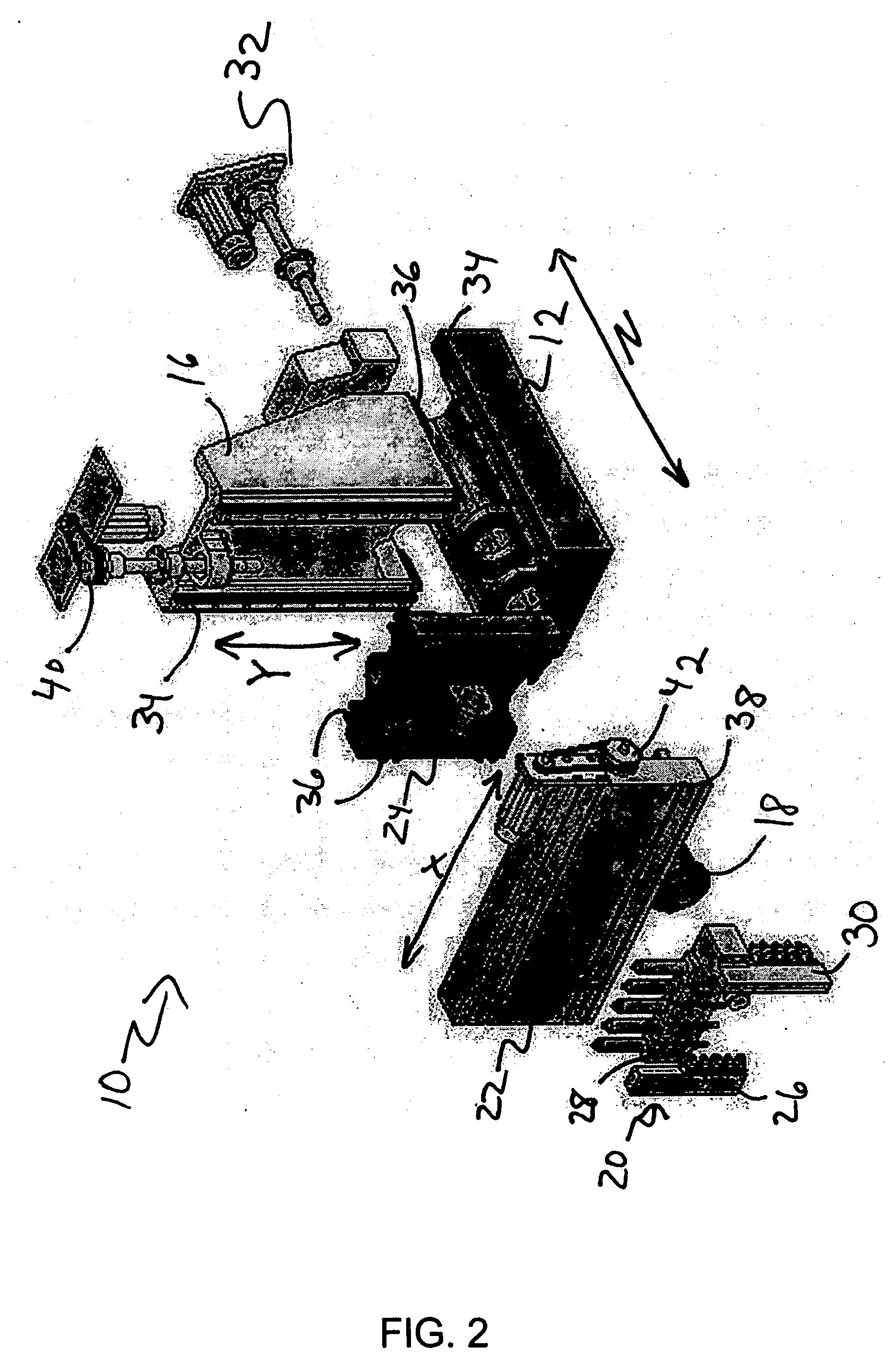
[0024] Referring now to the drawings, and more particularly to FIGS. 1, 2 and 3, there is shown a small parts machine tool according to the present invention. The small parts machine tool 10 is comprised of a base 12, an X carriage 22, a Y carriage 24, a Z carriage 16, and a tool holder system 20. The base 12 includes a spindle 18 at one end that secures and holds a workpiece to be machined. The spindle 18 holds the workpiece over the edge of the base. The spindle 18 also serves to rotate the workpiece in the C coordinate direction, which is designated by the arrow C in FIG. 1. This rotary motion may be indexed at desired rotational positions or provide a continuous rotary motion at a selected or variable speed.

[0025] The base 12 is further comprised of a sliding rail arrangement 14 that physically controls the direction of the Z carriage 16 along the Z coordinate direction, which is designated by the arrow Z. While the Figures show only linear motion guide ways as the exemplary sl...


PUM

PropertyMeasurementUnit
sizeaaaaaaaaaa
weightaaaaaaaaaa
flexibilityaaaaaaaaaa

Abstract

A compact, economical, and easy-to-use small parts machine tool that can machine small parts from bar stock as well as castings, forgings, slugs, and near net shape raw materials, is comprised a base with a spindle for moving a workpiece, a first carriage connected to the base that moves along a Z axial direction, a second carriage connected to the first carriage that moves along a Y axial direction, a third carriage connected to the second carriage that moves along an X axial direction, and a tool holder system that holds a plurality of machining tools.

Description

CROSS-REFERENCE TO RELATED APPLICATIONS [0001] This application claims priority to the provisional application filed May 16, 2005, having U.S. Provisional Patent Application Serial No. 60 / 681,136, and the complete contents of that application are herein incorporated by reference.BACKGROUND OF THE INVENTION [0002] 1. Field of the Invention [0003] The present invention generally relates to a tool for machining small component parts and, more particularly, to a compact, multi-axis, multi-tasking small part machine tool. [0004] 2. Background Description [0005] Practically every major industry today has the need for miniature component parts. For example, in the electronics and computer industries, smaller means faster information transfer, which results in higher input, output, and processing rates, and is particularly important in structures for mounting and interconnecting chips and for heat transfer. In the medical industry, smaller biomedical devices mean less invasive surgical proc...

Claims


Application Information

Patent Timeline
Patent Type & Authority Applications(United States)
IPC IPC(8): B23B39/16
CPCB23B3/065B23Q1/626B23Q39/027B23Q2039/006Y10T29/5114Y10T29/5126Y10T409/305656Y10T82/2524Y10T408/38
Inventor MILLER, LEE NORRIS
Owner MILLER LEE NORRIS
Why Eureka
Try Eureka