Composite pressure container or tubular body and composite intermediate

a pressure container and composite intermediate technology, applied in the field of composite intermediates, composite pressure containers, tubular bodies, etc., can solve the problems of long time to complete the winding, high operating costs, and difficulty in achieving the effect of fiber strength translation of hoop fibers

Inactive Publication Date: 2006-11-16
MITSUBISHI CHEM CORP
View PDF13 Cites 10 Cited by
  • Summary
  • Abstract
  • Description
  • Claims
  • Application Information

AI Technical Summary

Benefits of technology

[0017] Another object of the present invention is to provide a composite pressure container or tubular body using a prepreg tow in which the fiber strength translation of a hoop fiber is improved.
[0018] Another object of the present invention is to provide a composite pressure container or tubular body using a prepreg tow, which can be produced in an ecologically friendly manner.
[0039] By the present invention, an ecologically friendly process is possible, and the fiber strength translation of a hoop fiber in a composite pressure container or tubular body is greatly improved.

Problems solved by technology

However, when producing large composite structures, for example, it takes a long time to complete the winding, and thus the use of the resins wherein the curing reaction proceeds at room temperature is a problem.
When metallic pressure containers are used in automobiles, operating costs are high, and payload must be limited.
One of the problems heretofore associated with the production of composite pressure containers is that the substantial tensile strength (as hoop strength) of a pressure container decreases relative to the reinforcing fiber tensile strength (strand tensile strength).

Method used


Image

  • Composite pressure container or tubular body and composite intermediate
  • Composite pressure container or tubular body and composite intermediate

Examples


example 1

[0109] One mole of polyethylene glycol having a molecular weight of 7000 was reacted with one mole of diglycidyl ether bisphenol-A which was 188 g per epoxy equivalent to form a copolymer having a weight average molecular weight of approximately 8,000. One kilogram of this copolymer was mixed with 11 kg of an epoxy mixture of EPON 828, EPON 1050 and EPON 1001F of Shell at a ratio of 45 / 45 / 10, to form a resin mixture. This resin mixture was uniformly mixed with 880 g of dicyandiamide and 440 g of 3-(3,4-dichlorophenyl)-1,1-dimethylurea. The average particle diameter of dicyandiamide and 3-(3,4-dichlorophenyl)-1,1-dimethylurea was 10 μm, to form a resulting resin mixture.

[0110] The resulting resin mixture was heated at 70° C., and poured into the same amount of deionized water held at 70° C., to form a solution. The solution was stirred at 1,500 rpm. The temperature was then decreased to 35° C. to form an emulsion. The amount of the copolymer added was approximately 8%.

example 2

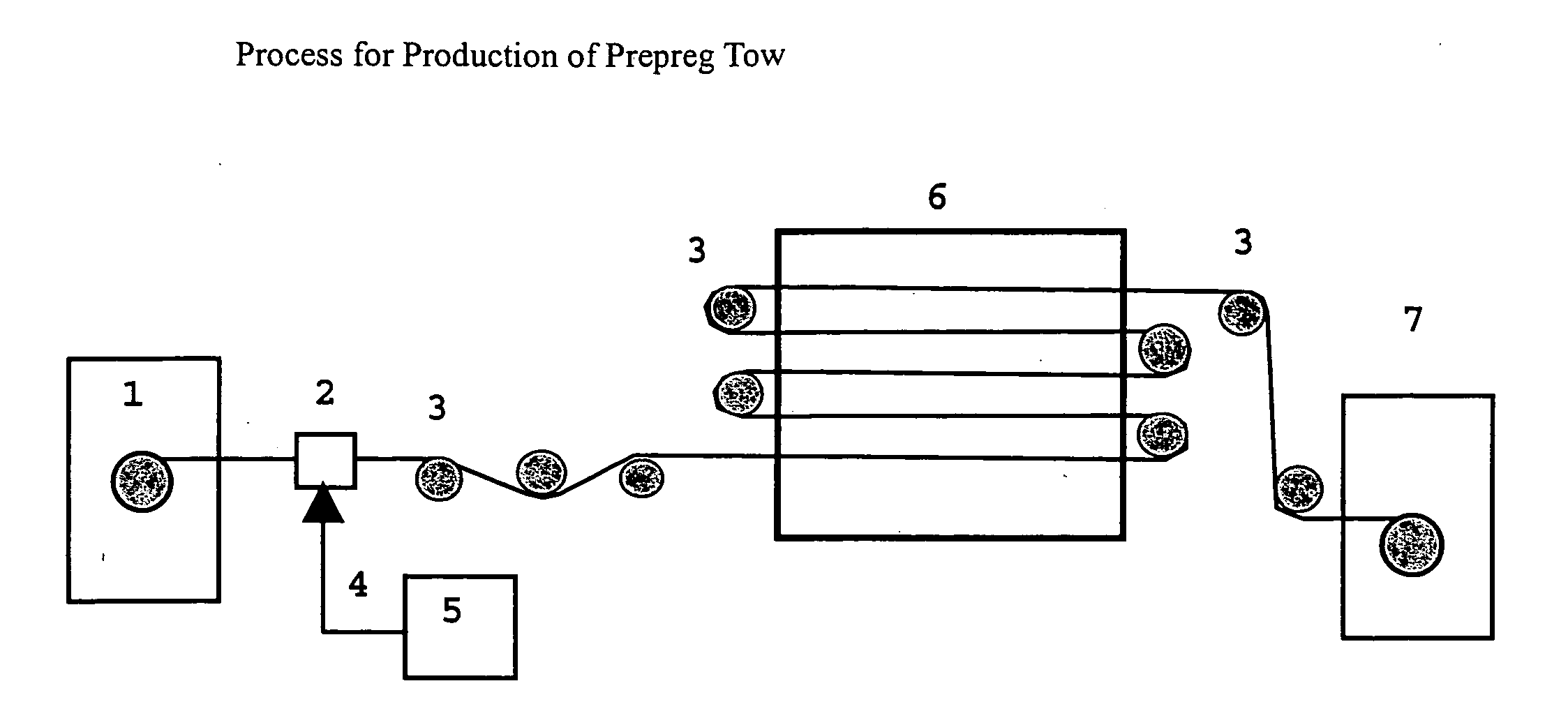
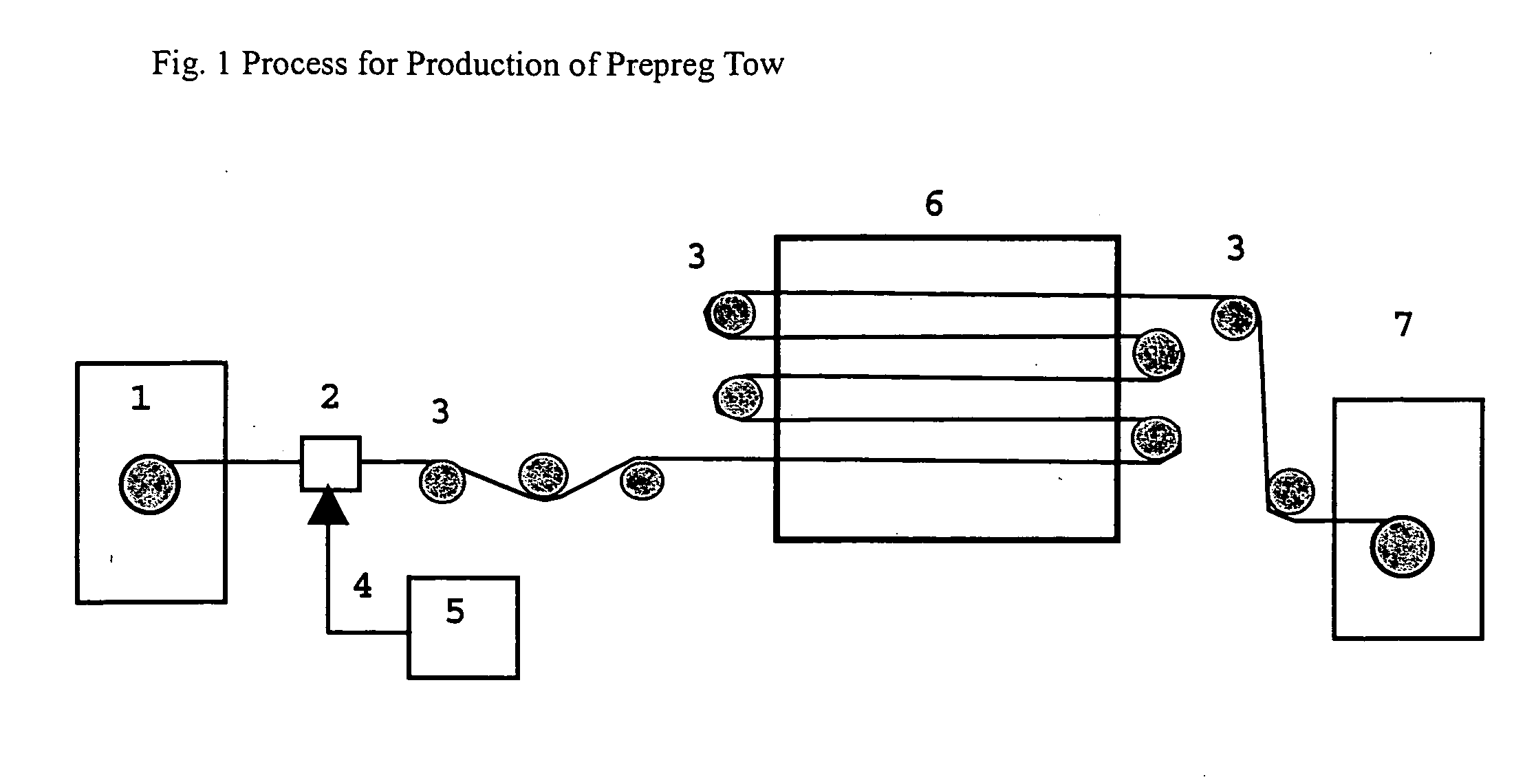
[0111] A prepreg tow was produced using a prepreg tow production apparatus shown in FIG. 1 using the emulsion formed in Example 1. The emulsion was charged in a resin tank 5, maintained at 35° C., and always stirred with a stirrer. The resin emulsion was fed to a resin impregnation device through a resin feed pipe 4 with a metering pump.

[0112] A spool of 12,000 filaments of carbon fiber TR50S manufactured by Mitsubishi Rayon Company Ltd. was installed in a creel. A carbon fiber tow was fed to the resin impregnation device and brought into contact with the resin fed from the resin tank. Subsequently, the fiber was impregnated with the resin through a resin impregnation roll, and water was then dried with an oven 6. The tow was wound with a winder 7. The production rate was 15 m / min, and the resin content was 30% by weight.

example 3

[0113] The prepreg tows produced in Example 2 were used, and they were arranged unidirectionally to form a unidirectional prepreg. Twelve plies of the prepreg were laminated, and cured in an autoclave at 275° F. for 2 hours to form a unidirectional laminate.

[0114] From the unidirectional laminate, test pieces for an interlaminar shear strength (SBS) and a 90° tensile strength (FS90) were prepared, and SBS and FS90 were measured according to ASTM D2344 and ASTM D790 (both incorporated herein by reference).

[0115] SBS and FS90 at 75° F. were 15 Ksi and 16 Ksi respectively.


PUM

PropertyMeasurementUnit
temperaturesaaaaaaaaaa
particle diameteraaaaaaaaaa

Abstract

One embodiment of the present invention relates to a composite pressure container or tubular body, which includes: a prepreg tow winding obtained by a process that includes: contacting at least one fiber with an uncured thermosetting resin, to form a coated fiber; winding said coated fiber around an outer shell, form, liner, or mandrel; and curing the resin; wherein said uncured thermosetting resin includes at least one surface active oligomer or polymer.

Description

BACKGROUND OF THE INVENTION [0001] 1. Field of the Invention [0002] The present invention relates to a composite pressure container, tubular body and / or composite intermediate produced using a prepreg tow process, reinforced fibers and prepreg tows for use in same, and methods of making and using same. [0003] 2. Discussion of the Background [0004] In recent years, composite molded articles have been increasingly used in applications such as CNG (compressed natural gas) tanks, breather oxygen tanks, e.g., for firefighters, hydrogen storage tanks, e.g., for fuel cells, off-shore pipes and flywheel rotors. These articles are generally produced by the filament winding method [0005] The filament winding method is suitable for the production of cylindrical or spherical molded articles, and it is quite advantageous because it facilitates automated manufacturing processes. This method also allows great reduction in the weight of the article, e.g., by replacing ordinary metals with a composi...

Claims


Application Information

Patent Timeline
Patent Type & Authority Applications(United States)
IPC IPC(8): B05D3/02F17C1/06B29B15/12B29C53/56B29C53/80B29C70/16B29C70/68B29K63/00B29L23/00B29L31/00F16J12/00
CPCB29B15/122B29C53/56Y10T428/1369B29L2031/712Y02E60/321B29C53/8066Y02E60/32
Inventor SANTO, IETSUGU
Owner MITSUBISHI CHEM CORP
Why Eureka
Try Eureka