Method of forming closed air gap interconnects and structures formed thereby
a technology of air gap and interconnect, which is applied in the direction of electrical equipment, semiconductor devices, semiconductor/solid-state device details, etc., can solve the problems of affecting the speed and thereby chip performance of the chip, the difficulty of placing a bridge layer on top of the extracted structure, and the general difficulty of reducing to practice, so as to maximize the air gap volume fraction, increase the performance, and minimize the amount of unsupported wiring
- Summary
- Abstract
- Description
- Claims
- Application Information
AI Technical Summary
Benefits of technology
Problems solved by technology
Method used
Image
Examples
first embodiment
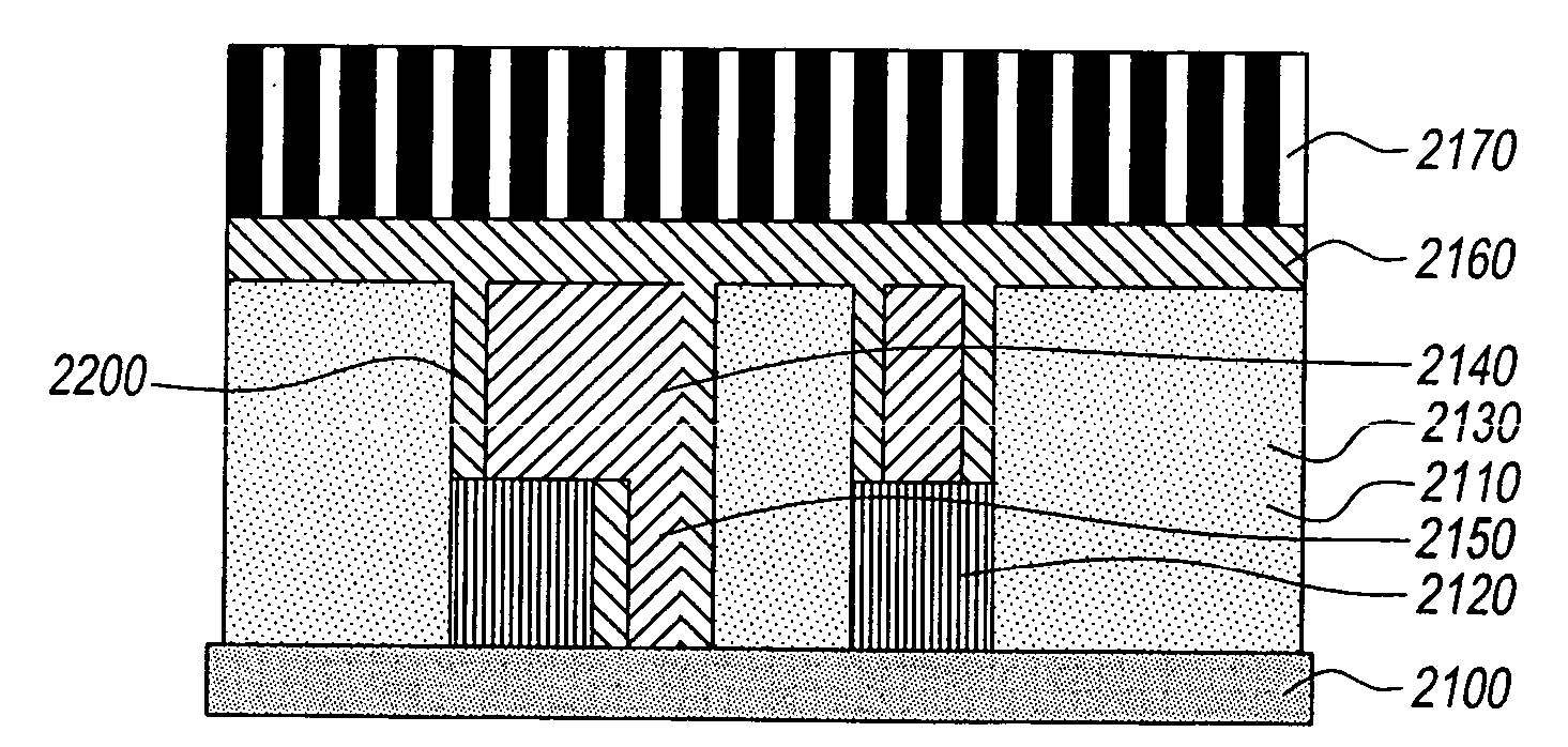
[0046] In the interconnect structure, the stencil with holes stays in place, holes are closed off by a cap dielectric. The structure has no hard mask or conformal dielectric passivation. The closed air gap interconnect structure includes: a substrate; a first sacrificial dielectric coated on the substrate, the first coated sacrificial dielectric having therein a patterned set of support regions formed by lithography and filled and planarized with a robust line support dielectric, the first sacrificial dielectric having therein contact via holes patterned by reactive ion etching; a second sacrificial dielectric coated on the first sacrificial dielectric and the filled and planarized support regions, the second sacrificial dielectric having lithographically patterned line trenches; a conductive material filled into the line trenches and the via holes and planarized; and a stencil with a regular array of holes on the filled line trenches and the second sacrificial dielectric; wherein t...
fourth embodiment
[0049] In the interconnect structure, the stencil with holes stays in place and the structure has a selective metal cap. The holes are closed off by a cap dielectric. The structure has no hard mask or conformal dielectric passivation. The closed air gap interconnect structure includes a substrate; a first sacrificial dielectric coated on the substrate, the first coated sacrificial dielectric having therein a patterned set of support regions by lithography and filled and planarized with a robust line support dielectric, the first sacrificial dielectric having therein contact via holes patterned by reactive ion etching; a second sacrificial dielectric coated on the first sacrificial dielectric and the filled and planarized support regions, the second sacrificial dielectric having lithographically patterned line trenches; a conductive material filled into the line trenches and the via holes and planarized; an optional conductive material cap disposed on top surfaces of the conductive m...
PUM
 Abstract
Description
Claims
Application Information
 - R&D
- Intellectual Property
- Life Sciences
- Materials
- Tech Scout
- Unparalleled Data Quality
- Higher Quality Content
- 60% Fewer Hallucinations
Browse by: Latest US Patents, China's latest patents, Technical Efficacy Thesaurus, Application Domain, Technology Topic, Popular Technical Reports.
© 2025 PatSnap. All rights reserved.Legal|Privacy policy|Modern Slavery Act Transparency Statement|Sitemap|About US| Contact US: help@patsnap.com


