Aircraft with disengageable engine and auxiliary power unit components

a technology of auxiliary power unit and disengageable engine, which is applied in the direction of engine components, machines/engines, mechanical apparatus, etc., can solve the problems of not always successful normal apu start, and achieve the effects of preventing further damage to these components, improving the apu start in the flight, and considerably improving the restart of the engin

Inactive Publication Date: 2006-11-23
MOULEBHAR DJAMAL
View PDF6 Cites 341 Cited by
  • Summary
  • Abstract
  • Description
  • Claims
  • Application Information

AI Technical Summary

Benefits of technology

[0010] During certain flight emergency conditions or abnormal flight situations, various engine or APU components can be taken off-line by use of the appropriate clutch. By this method, the disconnected component and its associated system can be saved from damage because during such an emergency this component will stop turning when it is disconnected. This component will therefore not need to be lubricated, which is a significant advantage because the lubricant (fuel, oil, or hydraulic fluid) will be shut off during the emergency or lost if there is leakage. During other emergencies and flight abnormal situations, by using a clutch that connects the component to the engine or APU gearbox, it is possible to disconnect the component, which is affected by the emergency condition from the engine or APU gearbox. Then, by using a second clutch it is possible to connect the gearbox component to an air turbine. The associated turbine of the engine gearbox component receives air from the engine secondary air flow (engine bypass air), ram air, APU air, or bleed air from operating engine(s), air from compressors attached the APU gearbox components (APU starter-generator and APU hydraulic pump), air from a compressor attached to the engine gearbox, or any appropriate combination of these sources (redundancy in air sources will assure at least the availability of one air source, like in case of the fan or both rotors get seized the engine bypass air is not available) through air valves. The associated turbine of the APU gearbox component (starter-generator or hydraulic pump) is supplied with ram air, operating engine(s), or any appropriate combination of air sources. The turbine drives the disconnected component so the component can provide emergency power (e.g., electric, hydraulic, or pneumatic) to certain critical

Problems solved by technology

To improve APU start in the flight, it is possible to connect an APU starter-generator and hydraulic pump, the related turbine, and the APU gearbox all together to provide the adequate

Method used


Image

  • Aircraft with disengageable engine and auxiliary power unit components
  • Aircraft with disengageable engine and auxiliary power unit components
  • Aircraft with disengageable engine and auxiliary power unit components

Examples


Embodiment Construction

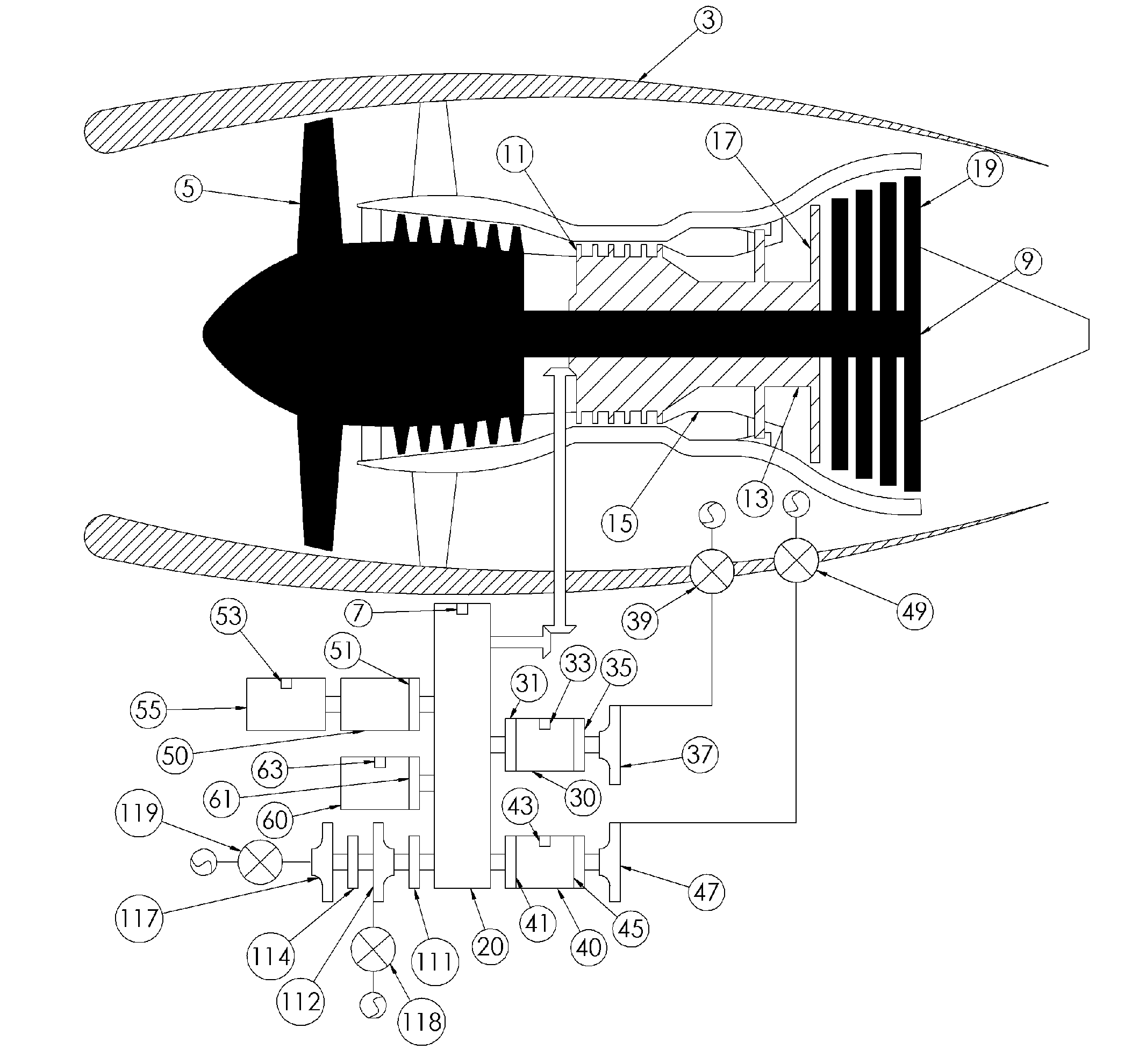
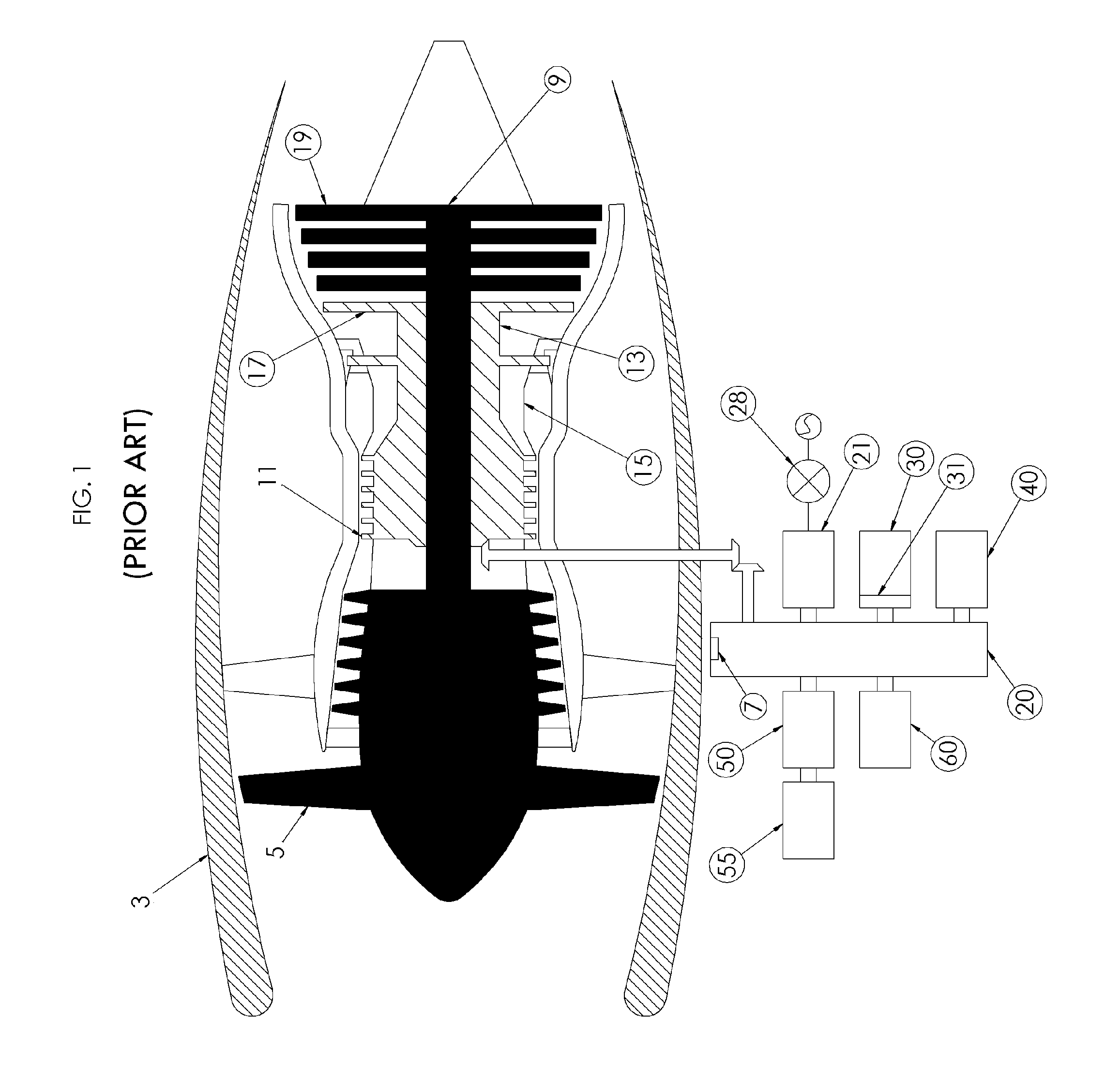
[0018]FIG. 1 depicts an aircraft gas turbine engine 3 (here, a turbofan engine) as it exists without any modifications from the present invention. The engine 3 includes a fan 5 that is driven by a low-pressure turbine (LP turbine) 19 through N1 shaft 9. A high-pressure turbine (HP turbine) 17 drives a high-pressure compressor (HP compressor) 11 through N2 shaft 13 by means of thermal energy from the combustion of fuel in a combustor 15. The HP compressor 11 drives a gearbox 20 that supplies mechanical power to the following components: an integrated drive generator (IDG) 30 and its clutch 31, an engine driven pump (EDP) 40, a fuel pump 50, a hydro-mechanical unit (HMU) 55, and an oil pump 60. A pneumatic starter 21 is supplied with air through start valve 28 to start the engine 3. The engine gearbox 20 is fitted with cranking pad 7.

[0019]FIG. 4 shows that, as part of the invention, in addition to the already existing clutch 31, the IDG 30 is fitted with a clutch 35, a cranking pad ...


PUM


Abstract

Several improvements to an aircraft turbine engine and Auxiliary Power Unit (APU) are disclosed, as well as methods of using these improvements in routine and emergency aircraft operations. The improvements comprise the addition of cockpit-controllable clutches that can be used to independently disconnect the engine's integrated drive generator (IDG), engine driven pump (EDP), fuel pump, and oil pump from the engine gearbox. These engine components may then be connected to air turbines by the use of additional clutches and then powered by the turbines. Similar arrangements are provided for the APU components. Cranking pads, attached to various engine and APU components, are disclosed to provide a means for externally powering the components for testing purposes and to assist with engine and APU start. Detailed methods are disclosed to use the new components for routine ground-testing and maintenance and for the enhancement of flight safety, minimization of engine component damage, and extension of engine-out flying range in the case of an emergency in-flight engine shutdown.

Description

CROSS-REFERENCE TO RELATED APPLICATIONS [0001] This application claims the benefit of U.S. Provisional Application No. 60 / 594,929, filed May 19, 2005, which is incorporated herein by reference.BACKGROUND OF THE INVENTION [0002] 1. Field of the Invention [0003] The invention relates to methods and devices for improving the safety of flight operations of turbine-powered aircraft and the efficient maintenance of aircraft engines and auxiliary power units (APU's). [0004] 2. Description of the Related Art [0005] Aircraft gas turbine engines particularly turbofan and APU comprise many components that require an adequate and proper maintenance to operate reliably and efficiently. In order to test or troubleshoot engine and APU components and systems, it is usually necessary to run the engine or the APU. This leads to many safety hazards around engines, APU, and aircraft and increases the use of fuel and the amount of resulting pollutants that enter the atmosphere. For example, it is not al...

Claims


Application Information

Patent Timeline
IPC IPC(8): F02C6/00
CPCF01D21/003F01D25/36F02C6/06F02C6/08F02C7/266F05D2260/85F02C7/32F02C7/36F05D2260/4023F05D2260/80F02C7/268
Inventor MOULEBHAR, DJAMAL
Owner MOULEBHAR DJAMAL
Why Eureka
Try Eureka