Liquid crystal display device and electronic apparatus
a display device and liquid crystal technology, applied in static indicating devices, non-linear optics, instruments, etc., can solve the problems of insufficient fundamental solution, deterioration of visibility, and lowering image quality under indoor fluorescent light, etc., to achieve excellent visibility and secure visibility.
- Summary
- Abstract
- Description
- Claims
- Application Information
AI Technical Summary
Benefits of technology
Problems solved by technology
Method used
Image
Examples
embodiment modes
[0064] Hereinafter, the embodiment modes of the present invention will be described with reference to the accompanying drawings. However, it is to be understood that various changes and modifications will be apparent to those skilled in the art. Therefore, unless such changes and modifications depart from the scope of the invention, they should be construed as being included therein.
embodiment mode 1
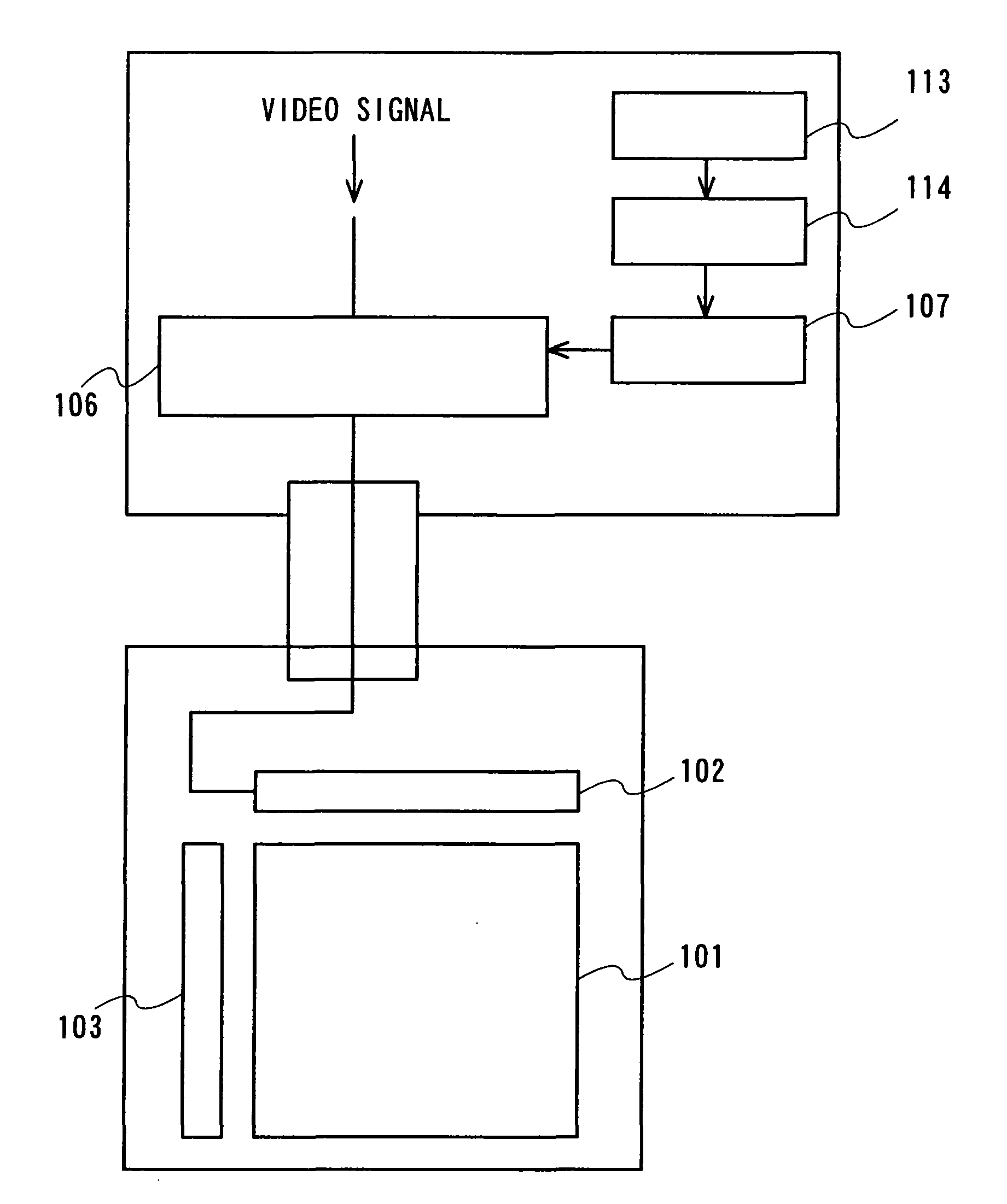
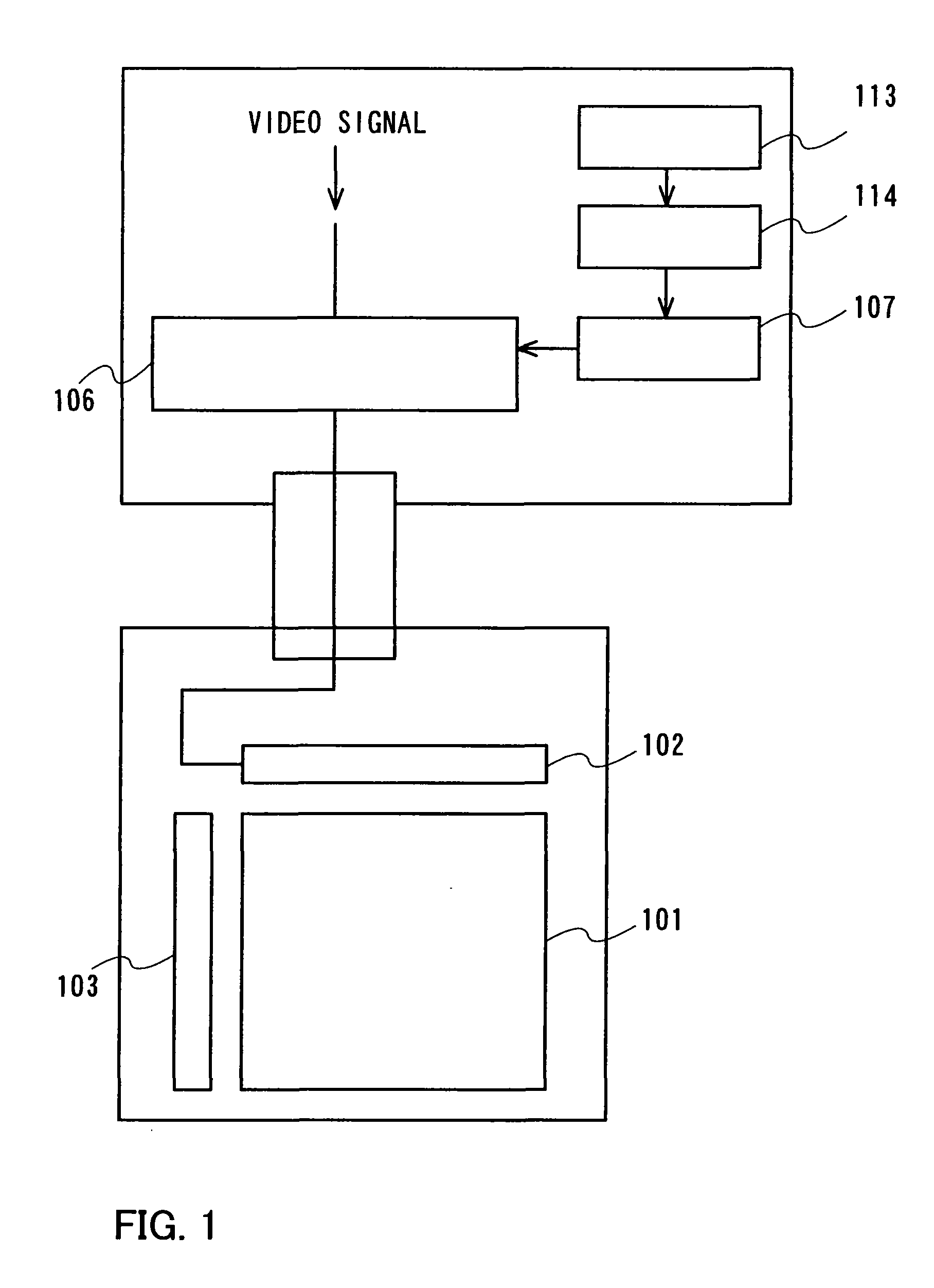
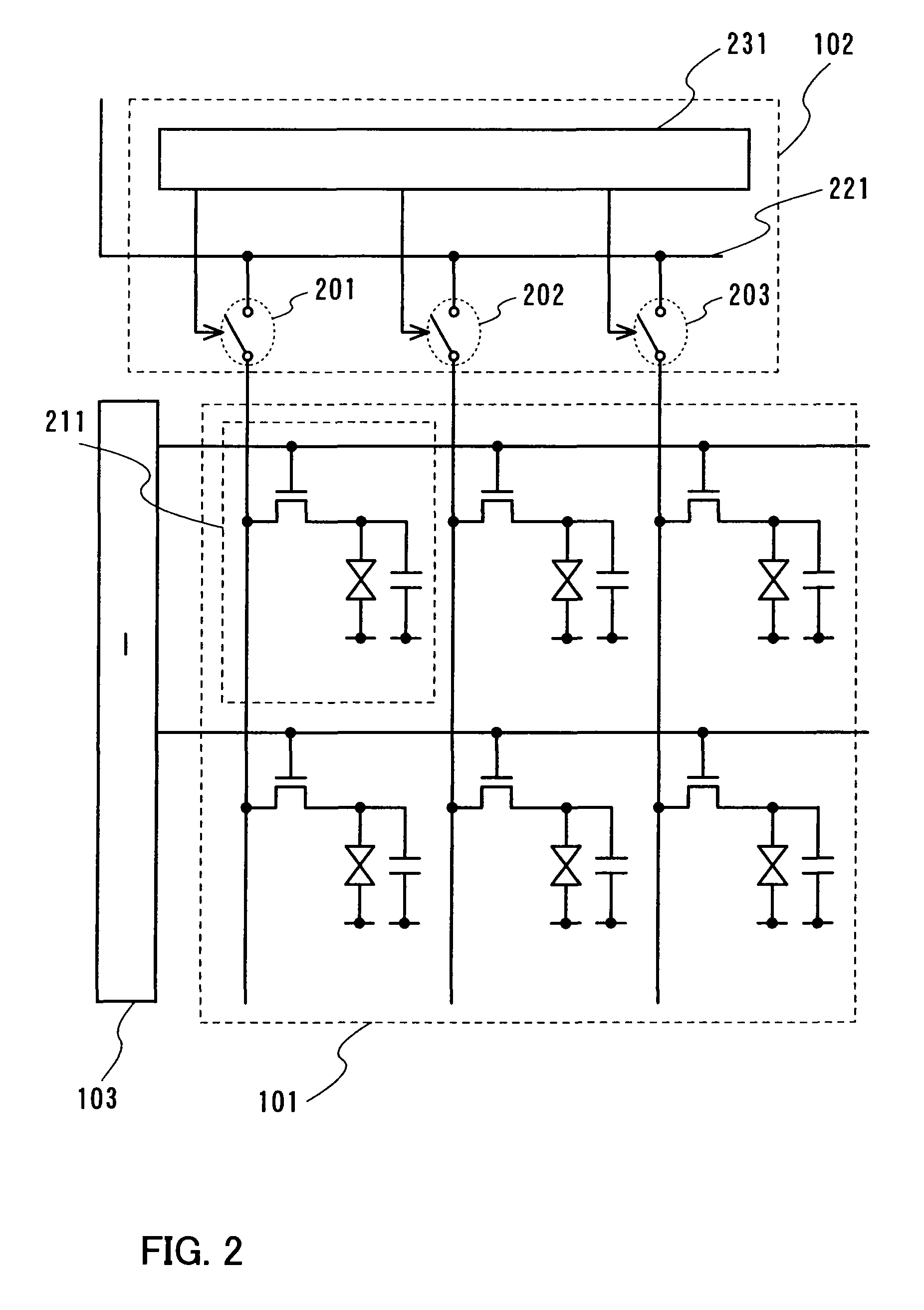
[0065]FIG. 1 is an entire block diagram. A source driver 102 and a gate driver 103 are provided for driving a pixel array 101. A video signal is inputted to the source driver 102. Note that a plurality of source drivers 102 and a plurality of gate drivers 103 may be provided.
[0066] An optical sensor 113 detects external light (external light which a display device receives). The output is supplied to an amplifier 114. The amplifier 114 amplifies an electrical signal that the optical sensor 113 outputs and the amplified electrical signal is supplied to a controller 107. When an electrical signal outputted by the optical sensor 113 outputs is large enough, the amplifier 114 is not required to be provided.
[0067] Note that a source driver or one portion thereof are not on the same substrate as the pixel array 101, and for example, using an external IC chip, and the source driver or one portion thereof can be composed.
[0068] Note that the amplifier 114 or the optical sensor 113 may be...
embodiment mode 2
[0116] Embodiment Mode 1 describes the case where a video signal to be inputted to the display mode-specific video signal generation circuit 106 is an analog value. Next, described is a case where a digital value is inputted.
[0117]FIG. 24 is an entire block diagram. A video signal to be inputted to the source driver 102 is generated in accordance with each display mode in a display mode-specific video signal generation circuit 2306. The display mode-specific video signal generation circuit 2306 is controlled using a controller 2307. Moreover, an original digital video signal is inputted to the display mode-specific video signal generation circuit 2306. Then, by using an original video signal, a video signal in accordance with each display mode is generated and outputted to the source driver 102 in the display mode-specific video signal generation circuit 2306.
[0118] An optical sensor 2313 detects external light (external light which a display device receives). The output is suppli...
PUM
 Abstract
Description
Claims
Application Information
 - R&D
- Intellectual Property
- Life Sciences
- Materials
- Tech Scout
- Unparalleled Data Quality
- Higher Quality Content
- 60% Fewer Hallucinations
Browse by: Latest US Patents, China's latest patents, Technical Efficacy Thesaurus, Application Domain, Technology Topic, Popular Technical Reports.
© 2025 PatSnap. All rights reserved.Legal|Privacy policy|Modern Slavery Act Transparency Statement|Sitemap|About US| Contact US: help@patsnap.com


