
Apparatus and method for FT pre-coding of data and control signals to reduce PAPR in a multi-carrier wireless network

Active Publication Date: 2006-11-23
SAMSUNG ELECTRONICS CO LTD
View PDF4 Cites 80 Cited by
  • Summary
  • Abstract
  • Description
  • Claims
  • Application Information

AI Technical Summary

Benefits of technology

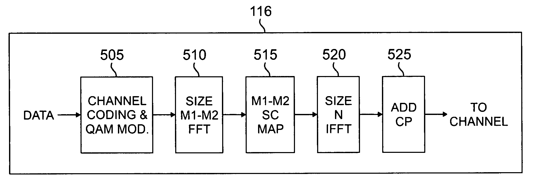
[0010] A method also is provided for reducing the peak-to-average power ration (PAPR) of a radio frequency signal transmitted by a subscriber station to a base station of a wireless network. The method comprises the steps of: receiving input symbols to be transmitted to the base station; performing a size M1 Fourier Transform (FT) operation on a first subset of the received input symbols to thereby generate M1 FT pre-coded outputs; performing a size M2 Fourier Transform (FT) operation on a second subset of the received input symbols to thereby generate M2 FT pre-coded outputs; and performing a size N inverse Fourier Transform (IFT) operation on N inputs, the N inputs including the M1 FT pre-coded outputs and the M2 FT pre-coded outputs, to thereby generate N outputs to be transmitted to the base station.

Problems solved by technology

Conventional power amplifiers for amplifying multi-carrier signals are relatively expensive parts of a communication system.
ACP noise results from signal distortion caused by operation of power amplifier components in non-linear regions of the input-output characteristic such as when the power amplifier enters saturation.
This distortion produces undesired spectral components in adjacent transmission channels.
However, a sudden large signal peak still results in distortion and ACP noise.
This is especially problematic in systems that have large peak-to-average power ratios (i.e., high crest factors), such as OFDM and OFDMA systems.
However, operating in back-off mode requires the use of devices with higher power ratings which adds to system design, development and manufacturing costs.
Furthermore, it may be inefficient and may generate excessive heat.

Method used


Image

  • Apparatus and method for FT pre-coding of data and control signals to reduce PAPR in a multi-carrier wireless network
  • Apparatus and method for FT pre-coding of data and control signals to reduce PAPR in a multi-carrier wireless network
  • Apparatus and method for FT pre-coding of data and control signals to reduce PAPR in a multi-carrier wireless network

Examples


Embodiment Construction

[0026]FIGS. 1 through 8, discussed below, and the various embodiments used to describe the principles of the present disclosure in this patent document are by way of illustration only and should not be construed in any way to limit the scope of the disclosure. Those skilled in the art will understand that the principles of the present disclosure may be implemented in any suitably arranged communication system.

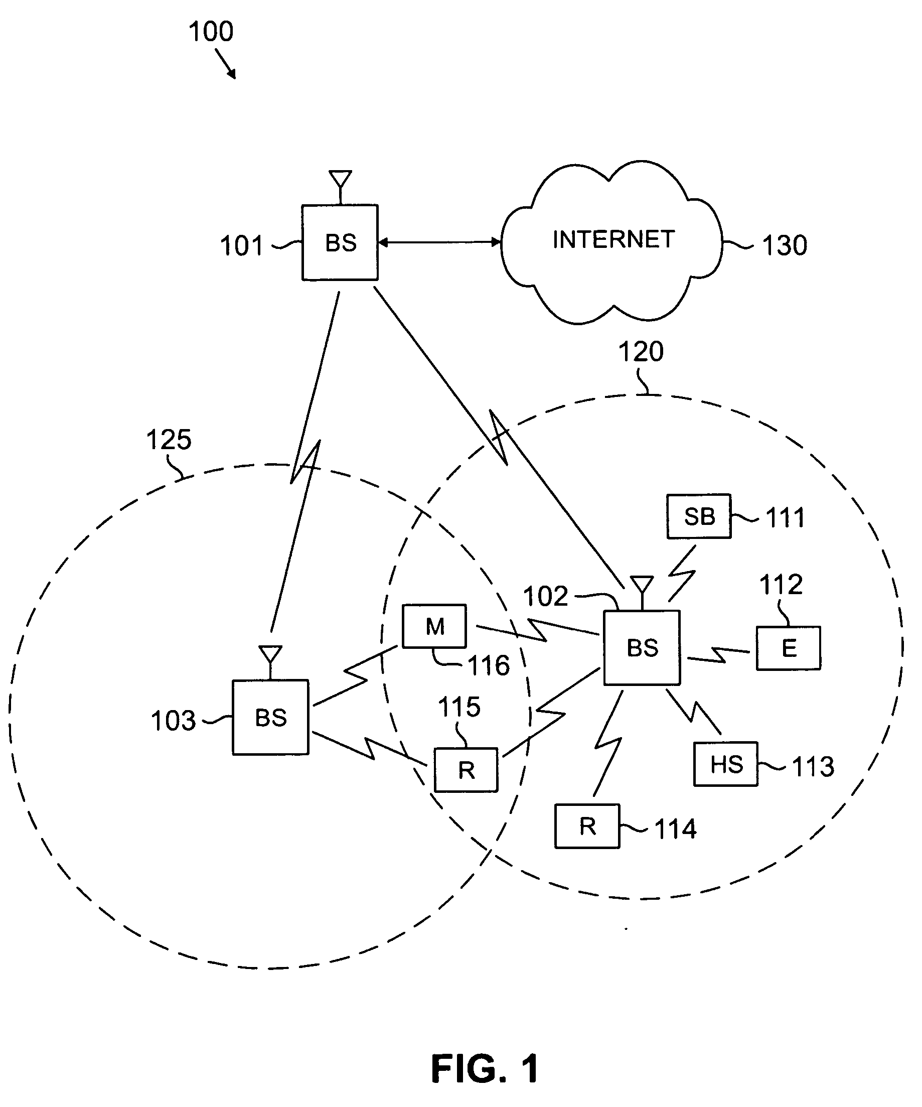
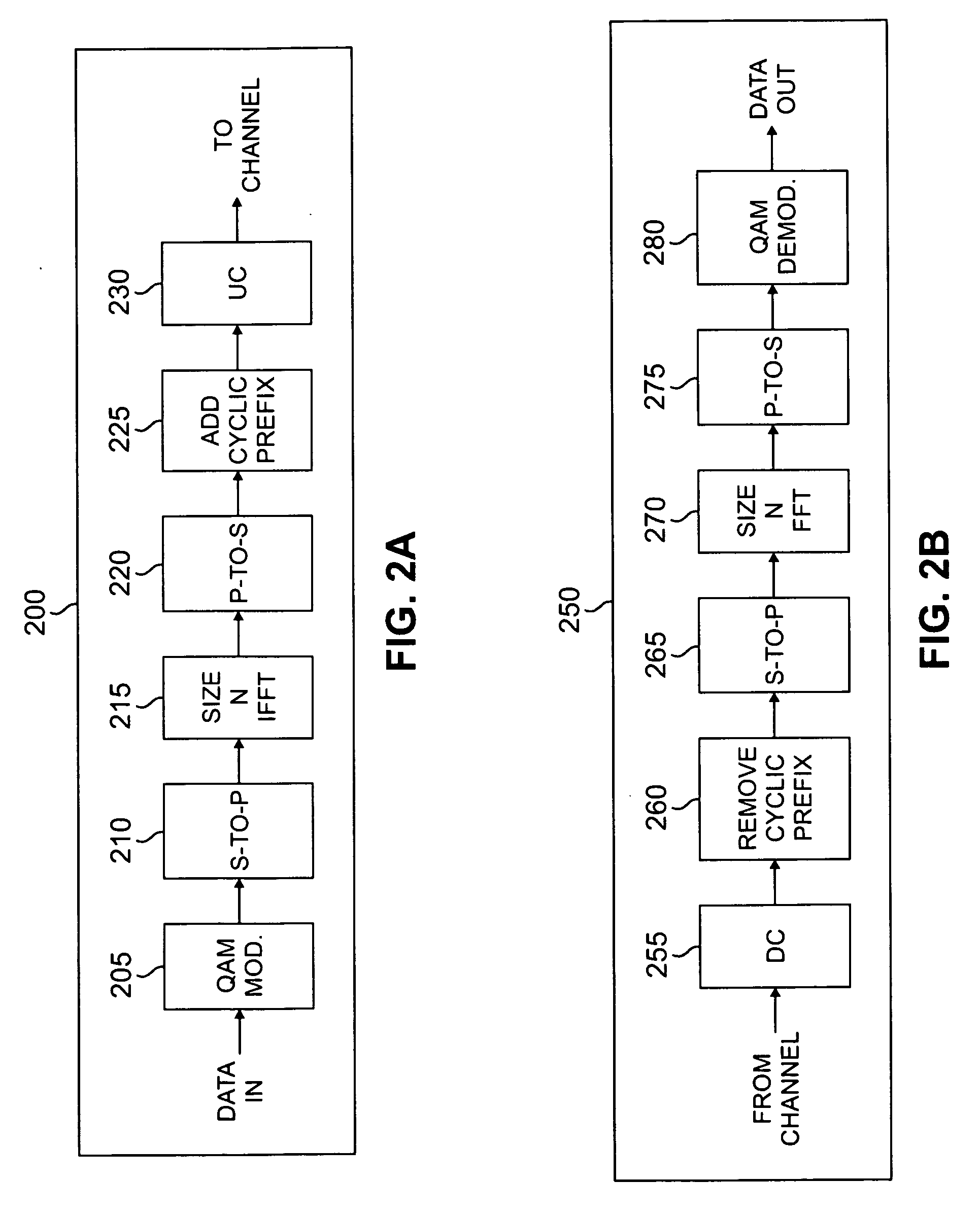
[0027] A transmission technique is disclosed for reducing the peak-to-average power (PAPR) ratio—or crest factor—of the transmitted waveforms for multi-carrier signals, such as orthogonal frequency division multiplexing (OFDM) or orthogonal frequency division multiple access (OFDMA) signals. Reducing PAPR provides improved power amplifier efficiency, reduced heat dissipation requirements, smaller heat sinks, reduced power supply load, and lower cost for wireless base stations and subscriber stations. In the descriptions that follow, it shall be assumed generally that transmitt...


PUM


Abstract

A subscriber station is provided for use in a wireless network communicating according to a multi-carrier protocol, such as OFDM or OFDMA. The subscriber station comprises: a size M1 Fourier Transform (FT) block that receives input symbols and generates M1 FT pre-coded outputs; a size M2 Fourier Transform (FT) block that receives input symbols and generates M2 FT pre-coded outputs; and a size N inverse Fourier Transform (IFT) block that receives N inputs, including the M1 FT pre-coded outputs and the M2 FT pre-coded outputs, and generates N outputs to be transmitted to a base station. The FT blocks are Fast Fourier Transform blocks or Discrete Fourier Transform blocks. The IFT block is an inverse Fast Fourier Transform block or an inverse Discrete Fourier Transform block.

Description

CROSS-REFERENCE TO RELATED APPLICATION AND CLAIM OF PRIORITY [0001] The present application is related to U.S. Provisional Patent No. 60 / 682,922, filed May 19, 2005, entitled “Multiplexing of FFT-Precoded Data and Signaling”. U.S. Provisional Patent No. 60 / 682,922 is assigned to the assignee of this application and is incorporated by reference as if fully set forth herein. The present application hereby claims priority under 35 U.S.C. §119(e) to U.S. Provisional Patent No. 60 / 682,922. CROSS-REFERENCE TO RELATED APPLICATION(S) [0002] The present application is related to U.S. Patent Application Serial No. [2005.04.002.WS0], entitled “Apparatus and Method for FT Pre-Coding of Data To Reduce PAPR in a Multi-Carrier Wireless Network,” filed concurrently herewith. Application Serial No. [2005.04.002.WS0] is assigned to the assignee of this application. The subject matter disclosed in Application Serial No. [2005.04.002.WS0] is incorporated by reference as if fully set forth herein. TECHN...

Claims


Application Information

Patent Timeline
IPC IPC(8): H04K1/10
CPCH04L27/2615H04L27/2614
Inventor KHAN, FAROOQ
Owner SAMSUNG ELECTRONICS CO LTD
Learn More