
Spinal repair

a technology for spinal nerves and implants, applied in the field of spinal nerve implants, can solve the problems of unhealthy pressure on other parts of the body, changes in the center of gravity of the body, and permanent discomfort, and achieve the effect of greater strength and/or stability

Inactive Publication Date: 2006-11-23
SPINAL VENTURES
View PDF45 Cites 476 Cited by
  • Summary
  • Abstract
  • Description
  • Claims
  • Application Information

AI Technical Summary

Benefits of technology

"The patent describes segmented implants for filling and distracting non-soft tissue cavities, particularly in the spine. The implants consist of interlockable segments that can be flexibly connected in a delivery configuration and then interlocked in a deployed configuration to form a stable structure. The implants can be used for anchoring devices and can be designed to be stable and provide strength and stability. The method of inserting the implant involves positioning an applicator and delivering the implant to the target tissue site, where it can be secured. The implants can be used for filling bone cavities and replacing a nuclear replacement device in the spine. The technical effects of the patent are the improved stability and strength of the segmented implants and the ability to securely anchor devices in the spine."

Problems solved by technology

Vertebral fractures may be painful and may deform the shape of the spine, resulting in unhealthy pressure on other parts of the body, loss of height, and changes in the body's center of gravity.
Untreated, such changes and the resulting discomfort can become permanent, since the bone heals without expanding the compression.
Existing methods of treating bone injuries may involve highly invasive or inadequate treatments.
When filling a bone cavity with bone filler using traditional vertebroplasty, fillers with lower viscosities may leak.
Further, even fillers having low viscosities may require the application of a high pressure to disperse the bone filler throughout the vertebral body.
However, application of high pressure also increases the risk of bone filler extravasation from the vertebral body.
Conversely, injecting a bone filler having a higher viscosity may provide an even greater risk of “leaking” bone filler into sensitive adjacent body areas.
Leaks or extrusion of the bone filler may be dangerous to a patient's health.
For example, posterior extravasation from a vertebral body may cause spinal cord trauma, perhaps resulting in paralysis.
Risk of leakage is even more acute when a bone filler is applied under pressure to expand a compression fracture, especially if the fracture has begun healing and requires substantial force to distract the cavity surfaces.
Furthermore, most bone cements and bone fillers are difficult to remove or to adjust.
Many bone cements, once set, are difficult or impossible to remove without further, highly invasive, surgery.
Even if the removal is attempted prior to the expiration of the setting time, the materials may have non-Newtonian flow characteristics requiring a substantial removal vacuum to achieve an initial and sudden movement.
However, the Grisoni device is not appropriate for spinal regions, and has many disadvantages.
Calcium sulfate hemihydrate (Plaster of Paris) and similar materials have low elasticity and crush strength, making them unreliable as materials to distract and later support a spinal region, particularly during the early stages of the healing process.
Filling materials that are readily compressed or crushed may shift within, or exit, the cavity altogether, leading to detrimental changes in the shape of the spinal region.
Materials with low crush strength are poor choices in withstanding the stress of distracting spinal regions, and may be unable to maintain the distracted shape after filling a spinal region.
Because the Baumgartner implant is elastic and somewhat amorphic, it may be less effective for filling and distracting spinal cavities, particularly cavities benefiting from implants having some stiffness, such as non-soft tissue cavities, and cavities that benefit from a stable implant shape.
However, Johnson's column of wafers is not amenable to providing uniform support to all surfaces of a cavity, when such support is needed.
Thus, these implants may be limited in strength and durability because of the inclusion of a releasable drug, as well as the properties and shape of the implant beads.
Current techniques and devices for spinal repair may be unsuccessful due to less bony endplate coverage, which translates into less load transfer and may result in loosening, shifting, and other failures of the treatment.
Successful interbody implants have been difficult for several reasons.
For example, a significant challenge in performing a successful interbody implant surgery is the small size of the entry portal providing access to the intervertebral region.
Achieving a long term final stabilization of the implant has also been a challenge.
However, these spacers can shift, leading to fusion failure.
Other devices have similar problems since none form a structure that cannot be independently shifted, such as a stable ring or circle.
Typical hydrogel replacements (e.g., commonly used for nucleus replacements) are large and thus require large entry ports.
Further, they also have a high failure rate due to implant slippage and / or displacement.
Thus, most existing devices or implants used for nucleus replacement are limited by the large portal dimensions required for implantation of the device, and also have a tendency to be quite unstable.
In order to accommodate the implant(s), a large access portal must be cut into the subject, resulting in pain, an extended recovery time, and damage to otherwise healthy tissue.

Method used


Image

  • Spinal repair
  • Spinal repair
  • Spinal repair

Examples


examples

[0175] In general, the implants and / or applicators described herein may be used to distract an existing body region. In one variation, the body region is a non-soft tissue cavity. In one variation, the body region is a hard tissue cavity, such as a bone cavity arising from a tumor, injury or surgery.

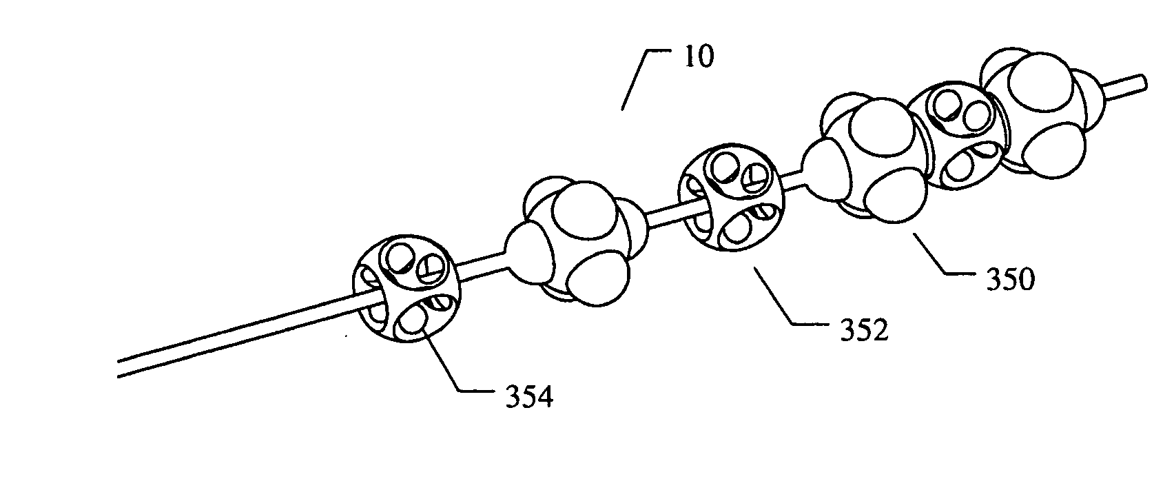
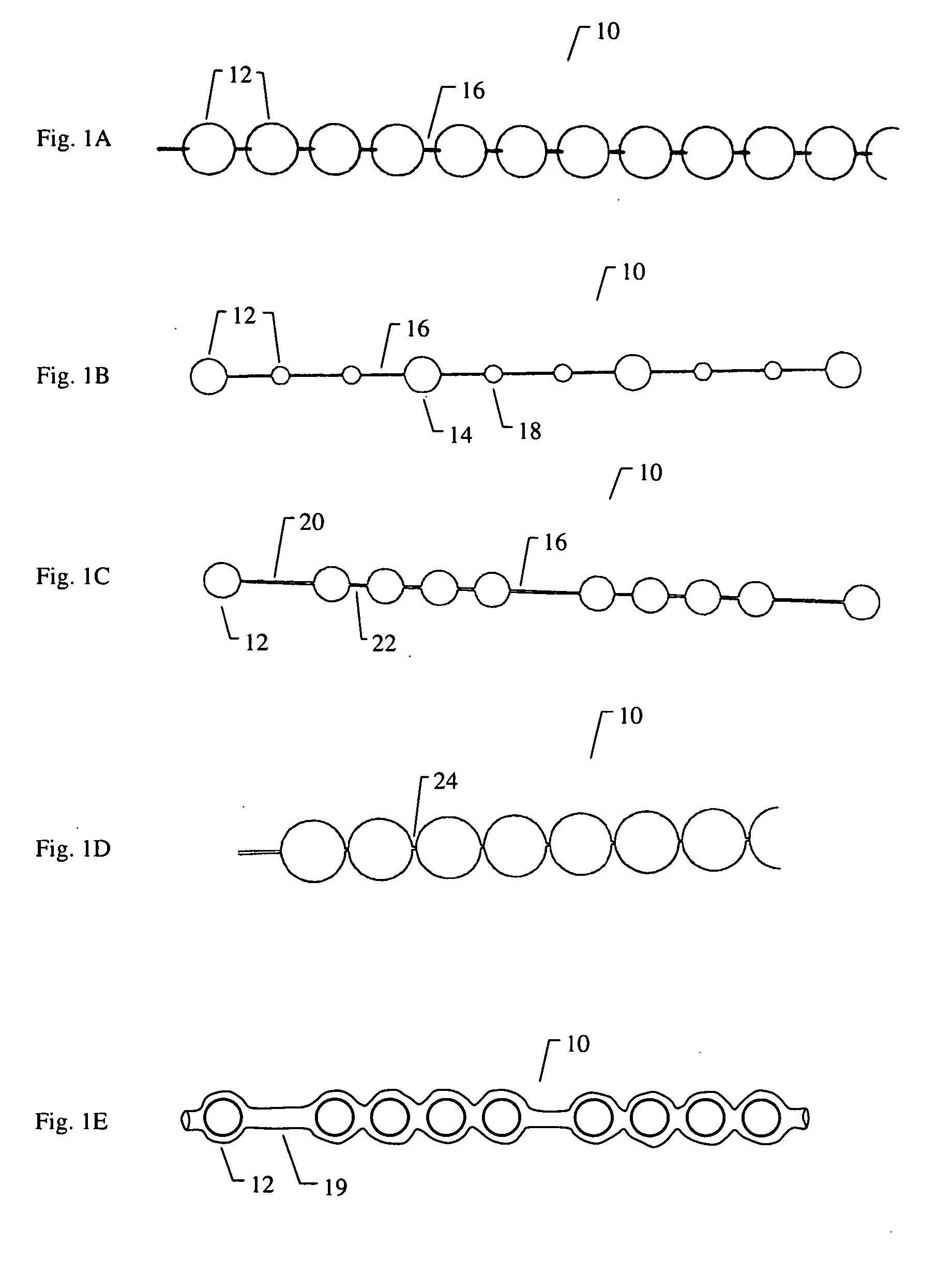
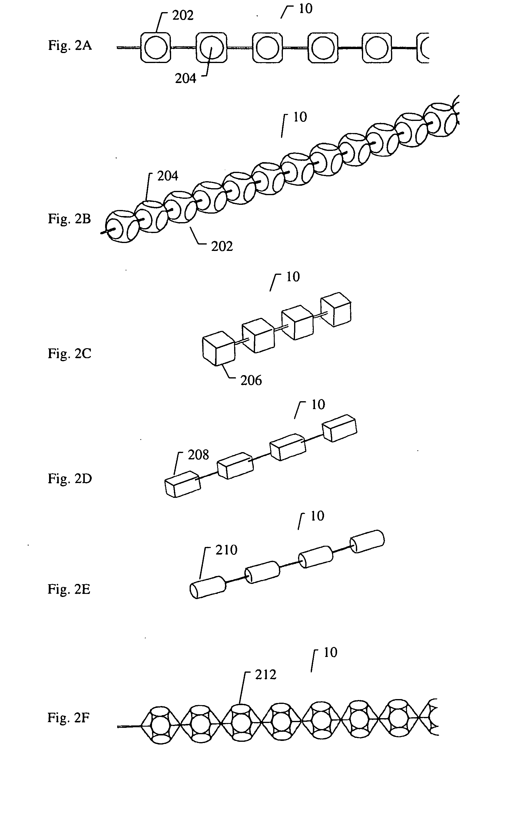
[0176]FIG. 8A to 8C shows an example of inserting an implant into a bone cavity 602. In this example, the bone cavity is part of a vertebral compression fracture. Other examples of bone disorders and fractures which may be distracted include, but are not limited to, tibial plateau fractures, femoral head necrosis, osteonecrosis of the hip, knee injury, etc. FIG. 8A shows an applicator 502 inserted into a vertebral compression fracture 804 through the vertebral pedicle 808; the applicator is inserting an implant 10 into the collapsed region. The implant is shown as a linear array of pellets 12. These segments of the implant may be continuously added to the bone cavity to first fill and p...


PUM


Abstract

A spinal implant for repairing a region of a subject's spine may have a plurality of interlockable segments that can be deployed from a delivery configuration (e.g., a linear array) into a deployed configuration. When the implant is in the delivery configuration, the implant comprises a linear array of the segments that are flexibly connected, and when the implant is in the deployed configuration, the segments are interlocked into a stable structure so that each segment is adjacent to and interlocked with at least two other segments. in the deployed configuration, the implants may have a greater strength (e.g., crush strength) and may help maintain the stability of the body region. The implant may be inserted into the spinal region by an applicator from the posterior region of the subject in the delivery configuration and assembled within the body to form the deployed configuration.

Description

CROSS-REFERENCE TO RELATED APPLICATIONS [0001] The present invention is related to and claims the benefit of U.S. Provisional Patent Application Ser. No. 60 / 655,829, filed Feb. 23, 2005, titled “METHODS AND APPARATUSES FOR FILLING A CAVITY II,” U.S. Provisional Patent Application Ser. No. 60 / 697,291, filed Jul. 6, 2005, titled “SPINAL REPAIR,” U.S. Provisional Patent Application Ser. No. 60 / 714,677, filed Sep. 7, 2005, titled “NON-SOFT TISSUE REPAIR,” and U.S. Provisional Patent Application Ser. No. ______ (not yet assigned), filed Nov. 23, 2005, titled “NON-SOFT TISSUE REPAIR II,” by Paul Zwirkoski, the disclosures of which are herein incorporated by reference in their entirety.FIELD [0002] Described here are spinal implants, implant applicators, delivery devices, and methods for using them. In particular, the description relates to implants having a plurality of interlockable, flexibly connected segments that may individually or once assembled have a strength sufficient to support...

Claims


Application Information

Patent Timeline
Patent Type & Authority Applications(United States)
IPC IPC(8): A61F2/44
CPCA61B17/7094A61F2/4611A61F2/4425A61F2002/2835A61F2002/302A61F2002/30331A61F2002/30383A61F2002/30462A61F2002/30495A61F2002/30604A61F2002/30662A61F2002/30663A61F2002/4415A61F2002/443A61F2002/444A61F2220/0025A61F2220/0033A61F2220/0075A61F2230/0065A61F2/442
Inventor ZWIRKOSKI, PAUL A.
Owner SPINAL VENTURES
Learn More